
Steel plate corner cutting device for high-end equipment manufacturing

A technology for equipment and steel plates, applied in the field of steel plate angle cutting devices for high-end equipment manufacturing, can solve the problems of time-consuming, labor-intensive, and low accuracy of manual operation, and achieve the effects of high safety, avoiding cutting failures, and avoiding accidental injuries.

Active Publication Date: 2021-10-22
邓芬芬
View PDF8 Cites 0 Cited by
  • Summary
  • Abstract
  • Description
  • Claims
  • Application Information

AI Technical Summary

Problems solved by technology

[0004] In order to overcome the time-consuming and labor-intensive manual cutting of steel plates and the low accuracy of manual operations, the technical problem is to provide a steel plate angle cutting device for high-end equipment manufacturing that can automatically clamp steel plates, cut steel plates, and have high precision.

Method used


Image

  • Steel plate corner cutting device for high-end equipment manufacturing
  • Steel plate corner cutting device for high-end equipment manufacturing
  • Steel plate corner cutting device for high-end equipment manufacturing

Examples


Embodiment 1

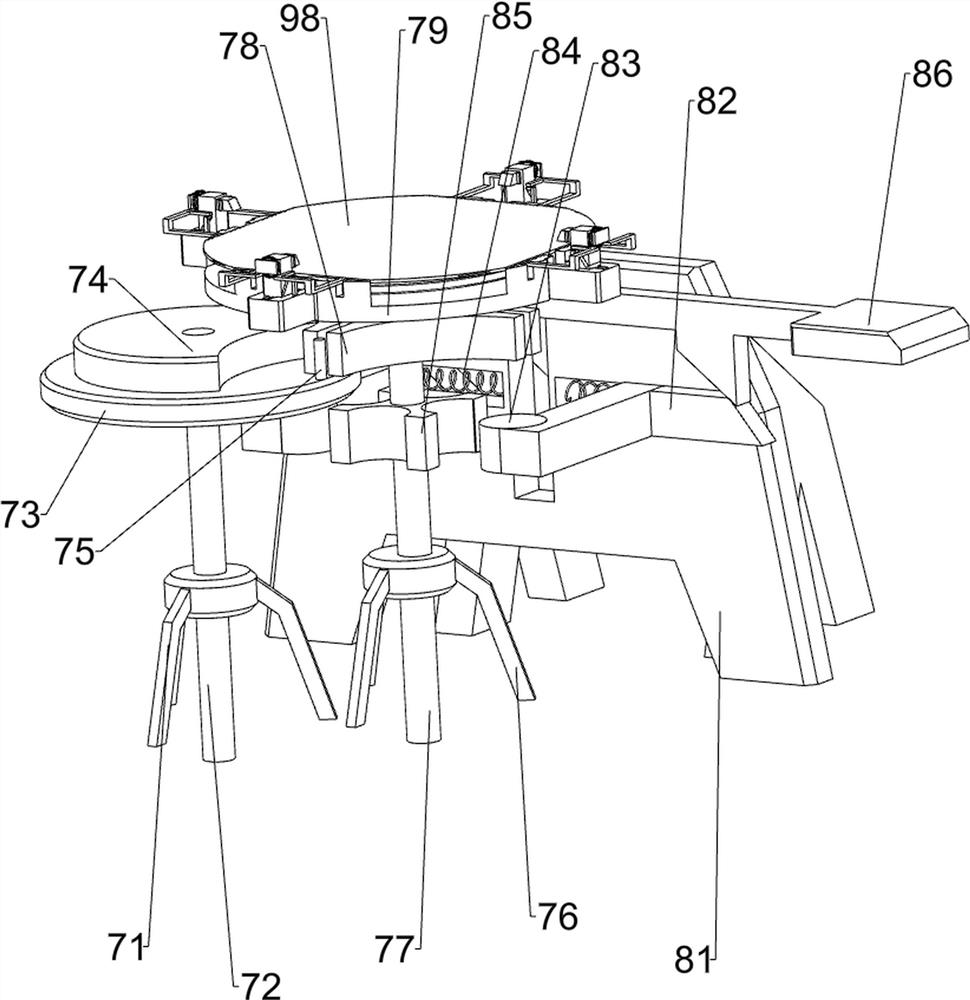
[0070] A steel plate chamfering device for high-end equipment manufacturing, such as figure 1 , figure 2 and Figure 5As shown, it includes a first fixed seat 1, a support frame 2, a first cylinder 3, a cutting machine 4, a transmission mechanism 6 and a rotating device 7, the top of the first fixed seat 1 is provided with a support frame 2, and the upper part of the support frame 2 is provided with The first cylinder 3, the lower part of the piston rod of the first cylinder 3 is provided with a cutting machine 4, the right side of the top of the first fixed base 1 is provided with a transmission mechanism 6, and the front side of the top of the first fixed base 1 is provided with a rotating device 7.

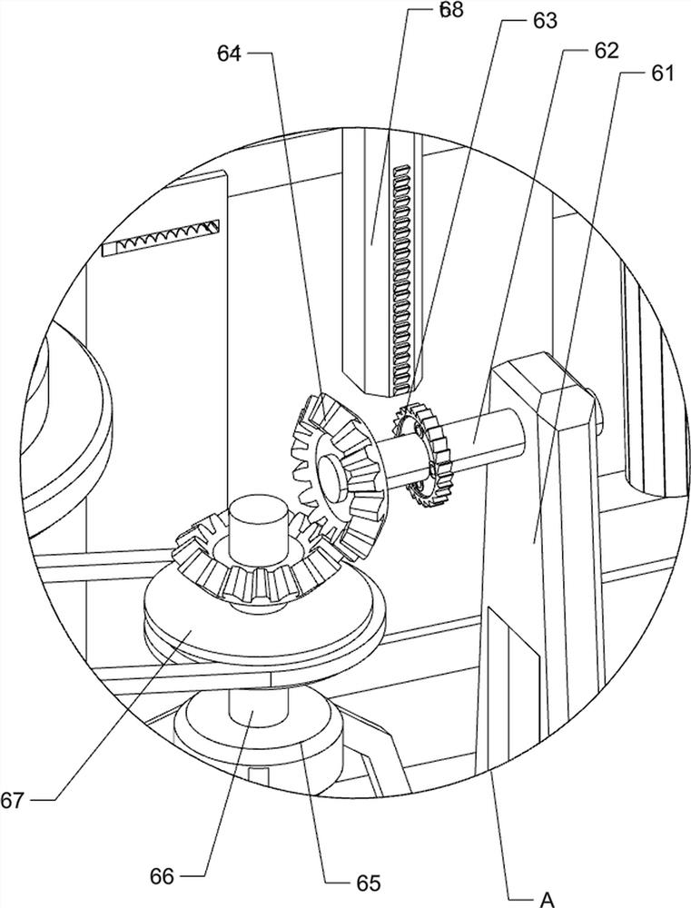
[0071] The transmission mechanism 6 includes a first fixed plate 61, a first transmission shaft 62, a one-way ratchet gear 63, a bevel gear 64, a first fixed leg 65, a first rotating shaft 66, a pulley set 67 and a ratchet rack 68, the first The middle part on the right side...

Embodiment 2

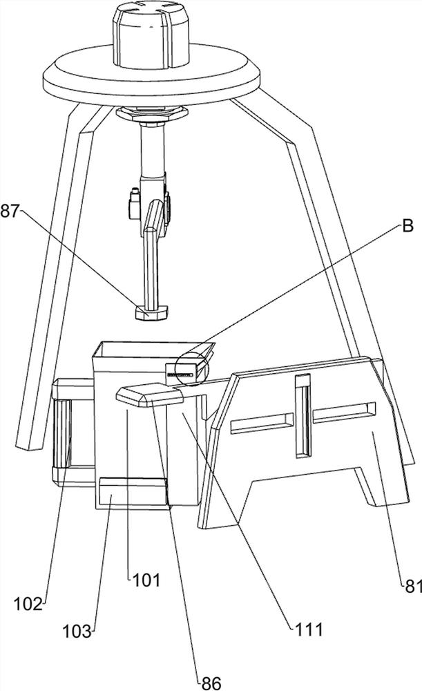
[0075] On the basis of Example 1, such as figure 2 , image 3 , Figure 4 and Figure 6 As shown, a brake device 8 is also included, and the brake device 8 includes a second fixed seat 81, a special-shaped wedge block 82, a brake block 83, a first spring 84, a special-shaped block 85, a first contact block 86 and a pressure rod 87, the left middle part of the top of the first fixed seat 1 is provided with a second fixed seat 81, and the front and rear symmetrical sliding type of the second fixed seat 81 top is provided with a special-shaped wedge block 82, and the right side of the special-shaped wedge block 82 is provided with a brake block 83, A first spring 84 is provided between the inner side of the special-shaped wedge block 82 and the second fixed seat 81, and a special-shaped block 85 is arranged in the middle of the third rotating shaft 77. The special-shaped block 85 cooperates with the brake block 83, and the upper middle of the second fixed seat 81 slides The f...


PUM


Abstract

The invention relates to a corner cutting device, in particular to a steel plate corner cutting device for high-end equipment manufacturing. According to the steel plate corner cutting device for high-end equipment manufacturing, a steel plate can be automatically clamped and cut, and the precision is high. The steel plate corner cutting device for high-end equipment manufacturing comprises a first fixing base, a supporting frame, a first air cylinder, a cutting machine, a transmission mechanism and a rotating device; the supporting frame is arranged at the top of the first fixing base; the first air cylinder is arranged at the upper part of the supporting frame; the cutting machine is arranged on the lower portion of a piston rod of the first air cylinder; the transmission mechanism is arranged on one side of the top of the first fixing base; and the rotating device is arranged on one side of the top of the first fixing base. According to the steel plate corner cutting device for high-end equipment manufacturing, through cooperation of the transmission mechanism, the rotating device and the cutting machine, the steel plate can be automatically rotated and cut, the working efficiency of people is improved, people can be prevented from being accidentally injured, and the safety is high.

Description

technical field [0001] The invention relates to a corner cutting device, in particular to a steel plate corner cutting device for high-end equipment manufacturing. Background technique [0002] The steel plate is a flat steel material that is poured with molten steel and then cooled and pressed. It can be directly rolled or cut from a wide steel strip. Steel plates can be divided into thin steel plates, medium-thick steel plates and extra-thick steel plates according to thickness, and thin steel plates can be divided into ordinary steel, high-quality steel, alloy steel, spring steel, stainless steel, tool steel, heat-resistant steel, bearing steel, silicon steel and industrial steel. Pure iron sheet, etc. [0003] Steel plates play a very important role in life. In different application scenarios, the size and shape of the steel plates that need to be used are different. Therefore, people need to cut the steel plates. In terms of current technology, the cutting is done manu...

Claims


Application Information

Patent Timeline
Patent Type & Authority Applications(China)
IPC IPC(8): B23D79/00B23Q3/00B23Q11/00
CPCB23D79/00B23Q3/00B23Q11/0042
Inventor 邓芬芬
Owner 邓芬芬
Learn More