Burr removing device for decorative plate processing

A technology for decorative plates and removal devices, which is used in metal processing equipment, grinding/polishing safety devices, machine tools suitable for grinding workpiece edges, etc. problem, to achieve the effect of accurate and reliable adjustment, avoiding horizontal slip adjustment, and convenient and quick adjustment

Pending Publication Date: 2021-10-22
XUZHOU WEICHANG WOOD
View PDF8 Cites 0 Cited by
  • Summary
  • Abstract
  • Description
  • Claims
  • Application Information

AI Technical Summary

Problems solved by technology

[0003] When the existing trimming machine is in use, the decorative plate to be processed is placed on the bracket assembly, and then the grinding wheel on the servo motor is used to grind and remove the burrs. During the processing, in order to ensure that the plates of different widths are placed on the bracket The component is not easy to tilt and tilt, and the movable frame fixed by the movable screw assembly on the bracket component can be adjusted, which has achieved the best supporting effect. However, in actual use, when adjusting the movable frame, the two screws need to be screwed separately. Only when the screw is loose can the sliding adjustment be carried out, which makes the adjustment inconvenient. At the same time, after the adjustment, the movable frame will easily slip during the screwing process, resulting in the inaccurate adjustment position. For this reason, we propose a decorative Deburring device for sheet metal processing

Method used


Image

  • Burr removing device for decorative plate processing
  • Burr removing device for decorative plate processing
  • Burr removing device for decorative plate processing

Examples


Embodiment 1

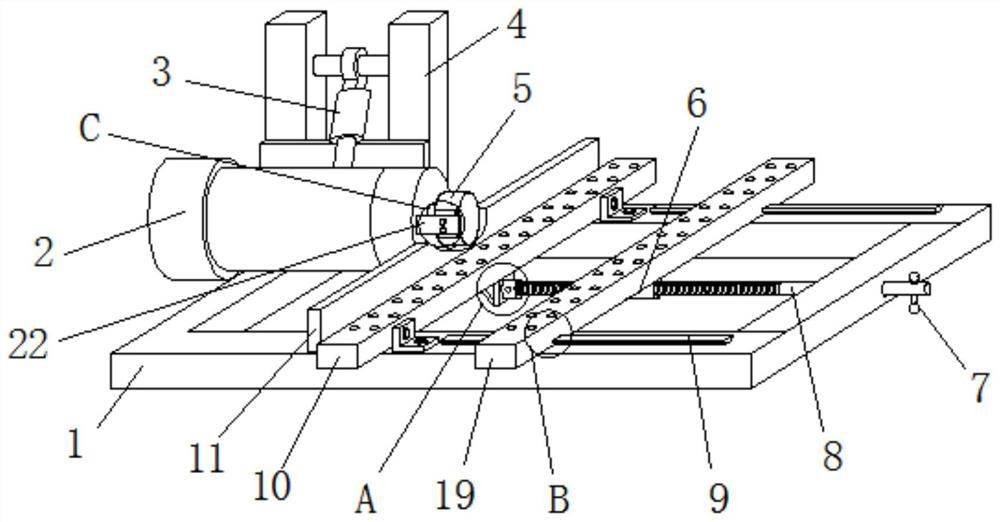
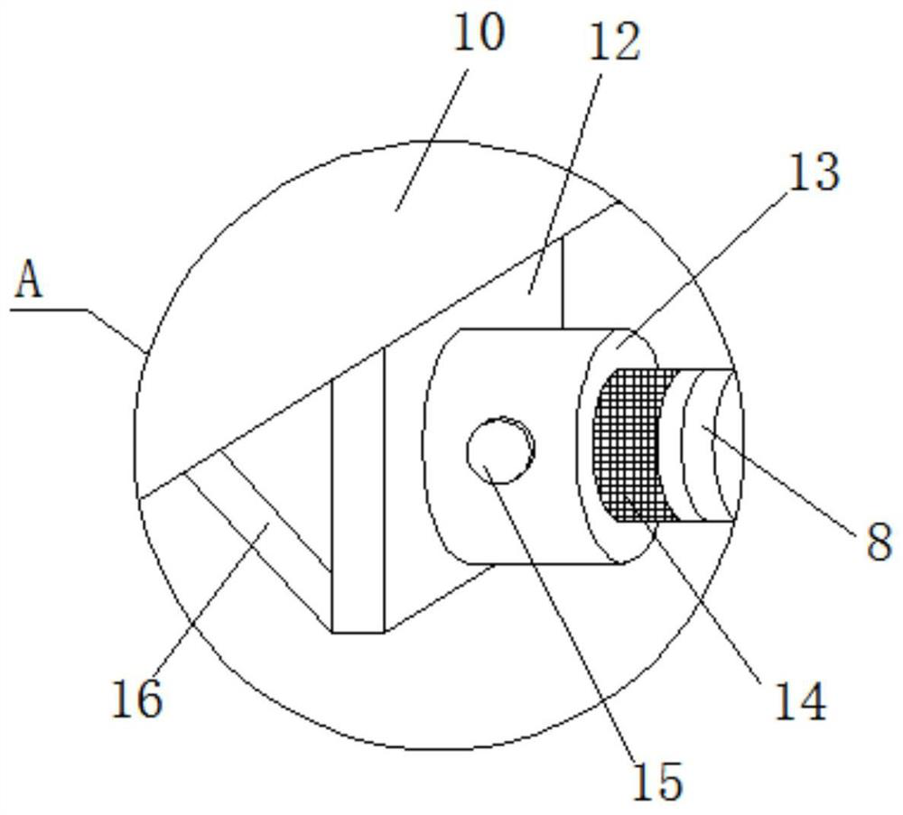
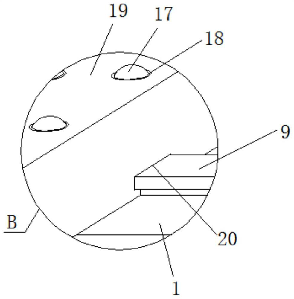
[0028] see Figure 1 to Figure 5 , the present invention provides a technical solution: a device for removing burrs for processing decorative panels, comprising a chassis 1, a bracket 4 is fixed on one side of the surface of the chassis 1, a servo motor 2 is arranged at the front end of the bracket 4, and the servo motor 2 and A hydraulic connecting rod 3 is connected between the supports 4, a grinding wheel 5 is fixed on the output end of the servo motor 2, and a fixing frame 10 is arranged on the bottom of the grinding wheel 5, and the fixing frame 10 is fixed on the surface of the chassis 1, and the fixing frame 10 One side is fixed with baffle plate 11, and the other side of fixed frame 10 is provided with movable frame 19, and the bottom end of movable frame 19 is fixed with spiral cylinder 6, and the inside of spiral cylinder 6 runs through threaded rod 8, and threaded rod 8 and spiral The cylinders 6 are connected by threads, one end of the threaded rod 8 runs through t...

Embodiment 2

[0032] see Figure 1 to Figure 5, the present invention provides a technical solution: a device for removing burrs for processing decorative panels, comprising a chassis 1, a bracket 4 is fixed on one side of the surface of the chassis 1, a servo motor 2 is arranged at the front end of the bracket 4, and the servo motor 2 and A hydraulic connecting rod 3 is connected between the supports 4, a grinding wheel 5 is fixed on the output end of the servo motor 2, and a fixing frame 10 is arranged on the bottom of the grinding wheel 5, and the fixing frame 10 is fixed on the surface of the chassis 1, and the fixing frame 10 One side is fixed with baffle plate 11, and the other side of fixed frame 10 is provided with movable frame 19, and the bottom end of movable frame 19 is fixed with spiral cylinder 6, and the inside of spiral cylinder 6 runs through threaded rod 8, and threaded rod 8 and spiral The cylinders 6 are connected by threads, one end of the threaded rod 8 runs through th...

Embodiment 3

[0037] see Figure 1 to Figure 7 , the present invention provides a technical solution: a device for removing burrs for processing decorative panels, comprising a chassis 1, a bracket 4 is fixed on one side of the surface of the chassis 1, a servo motor 2 is arranged at the front end of the bracket 4, and the servo motor 2 and A hydraulic connecting rod 3 is connected between the supports 4, a grinding wheel 5 is fixed on the output end of the servo motor 2, and a fixing frame 10 is arranged on the bottom of the grinding wheel 5, and the fixing frame 10 is fixed on the surface of the chassis 1, and the fixing frame 10 One side is fixed with baffle plate 11, and the other side of fixed frame 10 is provided with movable frame 19, and the bottom end of movable frame 19 is fixed with spiral cylinder 6, and the inside of spiral cylinder 6 runs through threaded rod 8, and threaded rod 8 and spiral The cylinders 6 are connected by threads, one end of the threaded rod 8 runs through t...


PUM


Abstract

The invention discloses a burr removing device for decorative plate processing. The burr removing device comprises a bottom frame, wherein a support is fixed to one side of the surface of the bottom frame; a servo motor is arranged at the front end of the support; a hydraulic connecting rod is connected between the servo motor and the support; a grinding wheel is fixed to the output end of the servo motor; and a fixing frame is arranged at the bottom of the grinding wheel and fixed to the surface of the bottom frame. Through the designed rotating column, threaded rod, spiral cylinder and movable frame, the spiral cylinder is fixed to the bottom of the movable frame, one end of the threaded rod is rotationally connected with a sleeve block through the rotating column, when the position of the movable frame is adjusted, only the threaded rod needs to be rotated to be in screwed with the spiral cylinder in a threaded manner, and the movable frame is driven to achieve horizontal adjustment. Therefore, the burr removing device is more convenient and faster to adjust. Meanwhile, the threaded rod and the spiral cylinder are connected through threads, so that good self-locking capacity is achieved, it is guaranteed that the position is fixed in time after adjustment is completed, and adjustment is more accurate.

Description

technical field [0001] The invention belongs to the technical field of board processing equipment, and in particular relates to a device for removing burrs for processing decorative boards. Background technique [0002] The trimming machine drives the grinding wheel to rotate through the motor, and grinds and removes the burrs produced by the side of the decorative panel after processing, so as to ensure smooth edges and corners of the panel and improve the aesthetics of the decorative panel. It is widely used in cabinets, wardrobes, door panels, etc. furniture industry. [0003] When the existing trimming machine is in use, the decorative plate to be processed is placed on the bracket assembly, and then the grinding wheel on the servo motor is used to grind and remove the burrs. During the processing, in order to ensure that the plates of different widths are placed on the bracket The component is not easy to tilt and tilt, and the movable frame fixed by the movable screw ...

Claims


Application Information

Patent Timeline
IPC IPC(8): B24B9/18B24B41/06B24B41/00B24B41/02B24B55/06
CPCB24B9/18B24B41/06B24B41/005B24B41/02B24B55/06
Inventor 李良林
Owner XUZHOU WEICHANG WOOD
Why Eureka
Try Eureka