
Steel pipe hoisting device for building construction

A hoisting device and building construction technology, applied in the direction of transportation and packaging, load hanging components, etc., can solve the problems of low steel pipe hoisting efficiency, frequent worker operations, and heavy labor, so as to reduce manual auxiliary installation, reduce manual operation, reduce artificial effects

Inactive Publication Date: 2021-10-22
裴志健
View PDF0 Cites 1 Cited by
  • Summary
  • Abstract
  • Description
  • Claims
  • Application Information

AI Technical Summary

Problems solved by technology

[0002] Scaffolding needs to be installed during construction, so scaffolding steel pipes need to be transported. At present, scaffolding steel pipes are stored in layers and cross-stacked. When in use, workers generally need to manually take them out for loading and transporting, or use a crane to cooperate with hoisting. Due to the limitation of the stacking method of steel pipes, there is no special lifting device at this stage, and the two ends of the steel pipes can only be hooked with wire ropes for hoisting. It can be realized by the cooperation of more than two workers, or the unstretched steel wire rope is directly inserted into the gap between the steel pipe layers, and the workers need to walk back and forth along one side of the pipe support during the whole process. The risk of steel pipe falling off increases during hoisting. Both methods have problems such as low steel pipe hoisting efficiency, frequent operations and heavy labor, and potential safety hazards. Therefore, at this stage, a more intelligent steel pipe hoisting device that can effectively save labor is needed to solve the above problems. question

Method used


Image

  • Steel pipe hoisting device for building construction
  • Steel pipe hoisting device for building construction
  • Steel pipe hoisting device for building construction

Examples


Embodiment Construction

[0020] The specific implementation manners of the present invention will be described in further detail below in conjunction with the accompanying drawings.

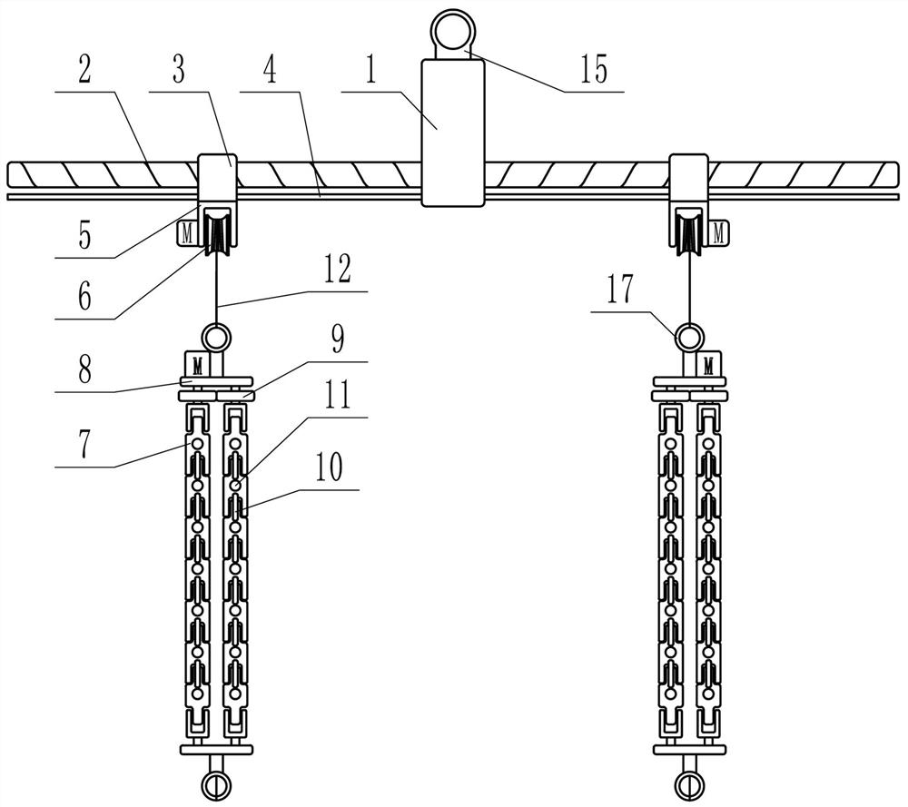
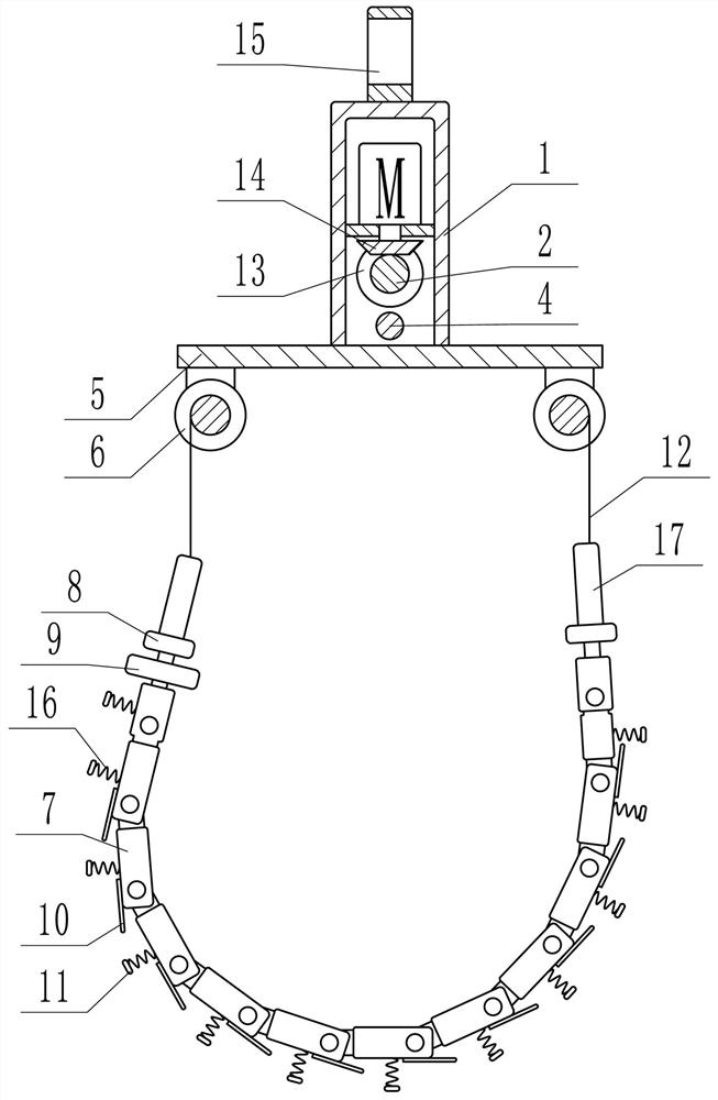
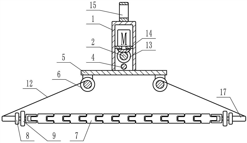
[0021] Depend on Figure 1 to Figure 5 It can be seen that the present invention includes a support frame 1, and a threaded rod 2 is installed horizontally through and rotated on the support frame 1. The screw threads on the left and right sides of the threaded rod 2 are in opposite directions, and the left and right sides of the threaded rod 2 are each screwed with a nut. 3. A guide rod 4 that runs through two nuts 3 and slides with the nuts 3 is fixed under the threaded rod 2. A support plate 5 is fixed at the lower end of each nut 3, and a support plate 5 is fixed at the front and rear ends of the support plate 5. Reels 6 that can be driven independently, two reels 6 on the same support plate 5 form a group, two parallel chains 7 are arranged under each group of reels 6, and a support is provided at each end of the ch...


PUM


Abstract

The invention relates to a steel pipe hoisting device for building construction. According to the technical scheme, the device comprises a supporting frame, a threaded rod transversely penetrates through the supporting frame and is rotationally installed on the supporting frame, supporting plates are rotationally installed at the left side and the right side of the threaded rod respectively, reels capable of being independently driven are fixed to the front end and the rear end of each supporting plate respectively, two parallel chains are arranged below each set of reels, and the ends of the chains are each provided with a supporting rod. The two ends of the chains are rotationally installed on the corresponding supporting rods through shafts, gears are coaxially fixed to the shafts at one ends of the chains, the two gears are meshed with each other, a limiting rod is fixed to the lower end face of each chain ring of the chains, the limiting rods enable the chains to only bend and deform upwards, a permanent magnet is fixed to the lower end face of each chain ring in the chains. When the two chains rotate until the permanent magnets on the chain rings are opposite, the multiple corresponding permanent magnets on the two chains attract each other, a rope is fixed to each reel, and the other end of each rope is fixed to the supporting rod at the corresponding side.

Description

technical field [0001] The invention relates to the field of building construction equipment, in particular to a steel pipe hoisting device for building construction. Background technique [0002] Scaffolding needs to be installed during construction, so scaffolding steel pipes need to be transported. At present, scaffolding steel pipes are stored in layers and cross-stacked. When in use, workers generally need to manually take them out for loading and transporting, or use a crane to cooperate with hoisting. Due to the limitation of the stacking method of steel pipes, there is no special lifting device at this stage, and the two ends of the steel pipes can only be hooked with wire ropes for hoisting. It can be realized by the cooperation of more than two workers, or the unstretched steel wire rope is directly inserted into the gap between the steel pipe layers, and the workers need to walk back and forth along one side of the pipe support during the whole process. The risk ...

Claims


Application Information

Patent Timeline
Patent Type & Authority Applications(China)
IPC IPC(8): B66C1/12B66C13/22
CPCB66C1/125B66C13/22
Inventor 裴志健
Owner 裴志健
Learn More