
Sludge collection and treatment equipment

A silt and equipment technology, applied in the field of silt collection and treatment equipment, can solve the problems of poor versatility of salvage scenarios, large water content in the silt, and low salvage efficiency, and achieve long-term efficient use, energy saving, and easy equipment avoidance. effect of loss

Inactive Publication Date: 2021-10-22
深圳市铭科科技有限公司
View PDF5 Cites 0 Cited by
  • Summary
  • Abstract
  • Description
  • Claims
  • Application Information

AI Technical Summary

Problems solved by technology

[0005] According to the different scene requirements of submerged salvage and dry salvage, according to the low salvage efficiency of submerged salvage and dry salvage, the water content of the silt collected by submerged salvage is high, and the generality of the salvage scene is not strong. Therefore, , we provide a collection and treatment equipment that can meet the needs of efficient salvage of sludge underwater or on the ground

Method used

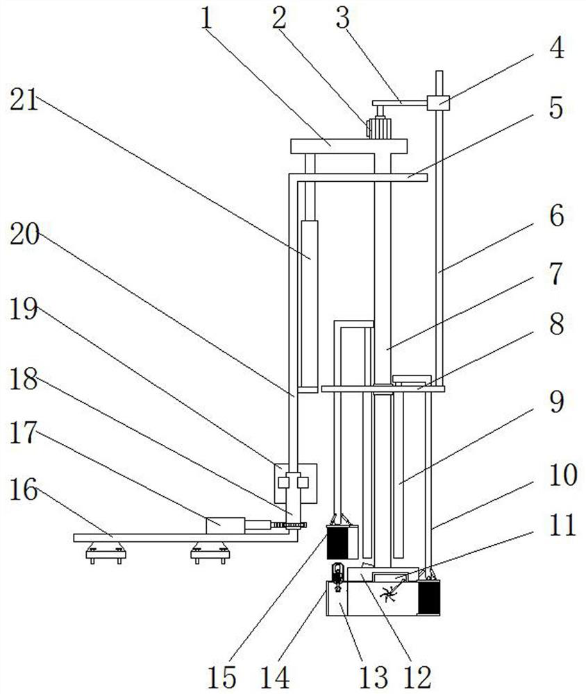
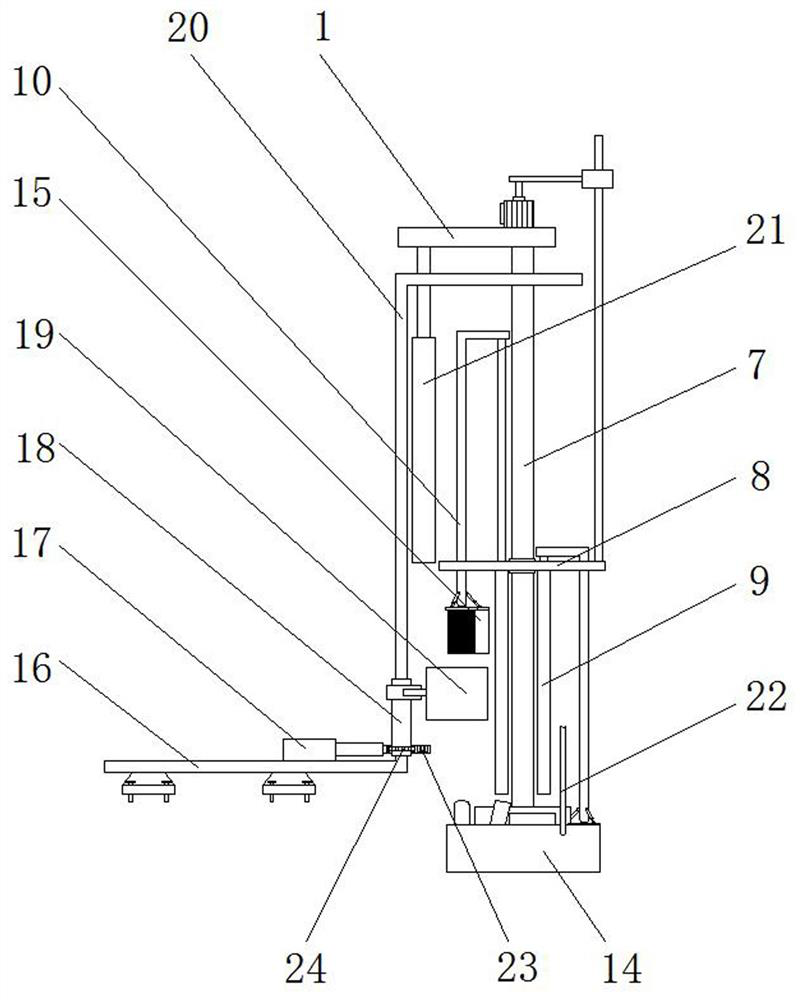
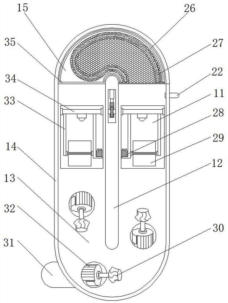

Image

  • Sludge collection and treatment equipment
  • Sludge collection and treatment equipment
  • Sludge collection and treatment equipment

Examples


Embodiment 1

[0028] See Figure 1-7In one embodiment of the present invention, a silt collection control device includes a fixing plate 16, and one end of the fixed plate 16 is perpendicularly welded to the column 20, and the column 20 is kept parallel to the fixed plate 16 welding. On the plate 5, the mounting plate 5 is vertically inserted with the main rod 7, and the main rod 7 is arranged parallel to the column 20, and the column 20 is equipped with a hydraulic cylinder 12 for driving the main roste 7 lifting and lowering. The output end extends to the mounting plate 5 and connected between the main rod 7, and the bottom end of the main roster 7 is welded to the separator 12, and the outer side welding of the separator 12 has a silt cover 14, the mud cover 14 and The partition 12 wall thickness is prone to the collection area after the sludge extrusion, that is, the thickness is large and the resistance is large and easy to affect the sealing. Therefore, the silt cover 14 and the bottom end...

Embodiment 2

[0030] The present embodiment differs from the first embodiment in that the outlet 35 of the top of the sludge 14 has a pair of symmetrical arrangement, and 4 of the secondary rod 10 and the silt collection assembly on the turntable 8, two or two silt collecting components. The servo on both sides of the inlet 35 is used alternately, i.e., two servo, one side of the projecting and exit 35, respectively, sludge collection and replacement, where the other two servo is used for silt collection and replacement, then When the rotation of the turntable 8 is reduced, the receiving component is also arranged in two groups, which can be more efficiently used for flow collection.


PUM


Abstract

The invention discloses sludge collection and treatment equipment which comprises a fixing plate; a stand column is vertically welded to one end of the top of the fixing plate, a mounting plate is welded to the end, away from the fixing plate, of the stand column and is parallel to the fixing plate, and a main lifting rod is vertically inserted into the mounting plate in a penetrating mode and is parallel to the stand column; a first hydraulic cylinder used for driving the main lifting rod to ascend and descend is mounted on the stand column in parallel. A stirring assembly and a receiving assembly are arranged, the medium injection pipe is connected to a sludge cover, a backflow cavity in the sludge cover can form a relatively closed space in the using process, outer side sludge and underwater soil are used for sealing, and the stirring assembly is matched to scatter the sludge after stretching and to collect and use sludge with different viscosity efficiently; and the receiving assembly is matched with lifting collection of a sludge collecting assembly, efficient and intelligent sludge containing and collecting are conveniently achieved, and the overwater labor intensity of operators is reduced.

Description

Technical field [0001] The present invention relates to the field of water conservancy engineering, and is specifically a silt collection and governance equipment. Background technique [0002] Silled is a natural water content greater than the fluid boundaries, and the pore is more than 1.5 soft soil, which is a modern sediment formed by the bay, the lake or the water flow in a slow environment. Contains organisms, often ash black, low mechanical intensity, strong compression. [0003] However, when the water body is contaminated, a part of the contaminated substance in the water can be adsorbed into the particles or depose themselves in the bottom mud, which is a potential pollution source for the lake. When the lake environment changes, the nutrient salt in the bottom mud may re-release, and it constitutes secondary pollution. Studies have shown that when the external pollution source of lakes, the main mud can become the primary pollution source. The release of seasonal nutri...

Claims


Application Information

Patent Timeline
IPC IPC(8): C02F11/121C02F11/00E02F5/28
CPCC02F11/121E02F5/28C02F11/00
Inventor 余俊祥胡凤苹陈浩荣
Owner 深圳市铭科科技有限公司
Learn More