
PCB drying device

A drying device and PCB board technology, applied in the field of PCB board manufacturing, can solve the problems of PCB board base damage, easy to be thrown, difficult to dry or dry, etc., to increase air flow, reduce local moisture, and improve drying rate Effect

Inactive Publication Date: 2021-10-22
ANHUI POLYTECHNIC UNIV MECHANICAL & ELECTRICAL COLLEGE
View PDF0 Cites 0 Cited by
  • Summary
  • Abstract
  • Description
  • Claims
  • Application Information

AI Technical Summary

Problems solved by technology

[0002] The PCB board needs to be dried during the board making process. Although the existing PCB board drying device can achieve drying to a certain extent, it still has the following defects: 1. Always blowing or drying at high temperature will cause PCB Board substrate damage; 2. Multiple PCB boards are placed in a material box at the same time, and the moisture on the inner PCB board is easily thrown on the adjacent outer PCB board, resulting in secondary wetting of the PCB board; 3. Often The drying of the PCB board is uneven, making it difficult to dry or dry the other parts

Method used


Image

  • PCB drying device
  • PCB drying device
  • PCB drying device

Examples


Embodiment

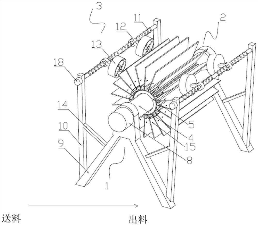
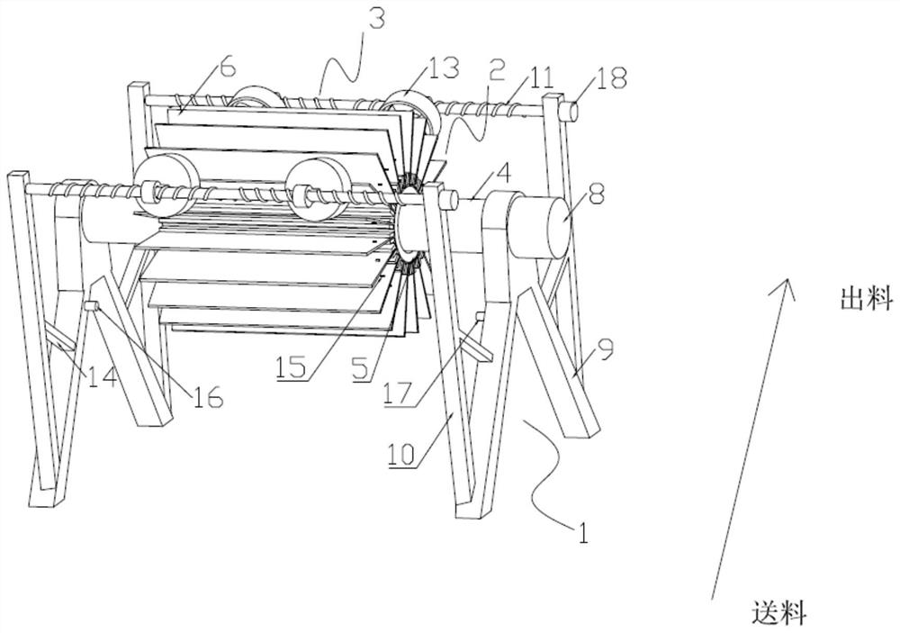
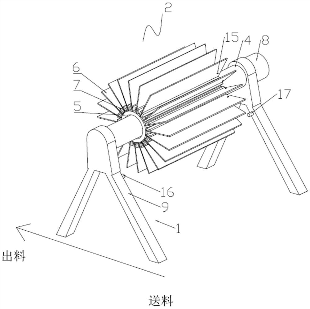
[0025] Such as Figure 1 to Figure 5 As shown, a PCB board drying device includes a frame 1, a transmission mechanism 2, and an air-drying mechanism 3;

[0026] The frame 1 is rotatably connected to the transmission mechanism 2, the transmission mechanism 2 includes a rotating shaft 4, a swivel 5, a receiving plate 6 and a slot 7, the rotating shaft 4 is rotatably connected to the frame 1 and connected to the No. 1 motor 8 The output shaft of the No. 1 motor 8 is installed on the frame 1, the rotating ring 5 is sleeved outside the rotating shaft 4 and arranged in a circular arrangement along its axial direction with several receiving plates 6 described above, and the adjacent two Slots 7 are installed between the receiving plates 6;

[0027] The air-drying mechanism 3 has two groups and is symmetrically distributed on both sides of the frame 1, wherein the air-drying mechanism 3 near the feeding end blows warm air, and the air-drying mechanism 3 near the discharging end blows...


PUM


Abstract

The invention discloses a PCB drying device, and relates to the field of PCB manufacturing. The PCB drying device comprises a rack, a conveying mechanism and air drying mechanisms; and the conveying mechanism comprises a rotating shaft, a rotating ring, a bearing plate and a slot; and the two sets of air-drying mechanisms are symmetrically distributed on the two sides of the rack, the air-drying mechanism close to the feeding end blows warm air, and the air-drying mechanism close to the discharging end blows cold air. According to the he PCB drying device, PCBs are blow-dried by the hot air and the cold air in the rotating process, the drying rate is increased, meanwhile, a PCB substrate is protected against high-temperature damage, two sections of threads with opposite screwing directions are arranged on one threaded rod, so that two fan systems on the same threaded rod can move close to or far away from each other in a reciprocating mode, air flow is increased, more drying area is covered, drying of the whole surface of a PCB is facilitated, and the situation of local drying and local wetting is reduced; and a humidity sensor is arranged to feed back a humidity signal, so that the PCB which is not blow-dried for the first time can be continuously rotationally conveyed and blow-dried for the second time.

Description

technical field [0001] The invention relates to the field of PCB board manufacturing, in particular to a PCB board drying device. Background technique [0002] The PCB board needs to be dried during the board making process. Although the existing PCB board drying device can achieve drying to a certain extent, it still has the following defects: 1. Always blowing or drying at high temperature will cause PCB Board substrate damage; 2. Multiple PCB boards are placed in a material box at the same time, and the moisture on the inner PCB board is easily thrown on the adjacent outer PCB board, resulting in secondary wetting of the PCB board; 3. Often The drying of the PCB board is uneven, which makes it difficult to dry or dry the other parts. [0003] Therefore, it is necessary to provide a PCB board drying device to solve the above problems. Contents of the invention [0004] In order to solve the problems of the technologies described above, the present invention provides th...

Claims


Application Information

Patent Timeline
Patent Type & Authority Applications(China)
IPC IPC(8): F26B11/18F26B21/00F26B25/00F26B25/02F26B25/04F26B25/22H05K3/22
CPCF26B11/18F26B21/001F26B21/004F26B25/003F26B25/02F26B25/04F26B25/22H05K3/227
Inventor 张松林
Owner ANHUI POLYTECHNIC UNIV MECHANICAL & ELECTRICAL COLLEGE
Learn More