Array substrate, display device and manufacturing method of display device

A technology for an array substrate and a display device, which is applied to the production of display devices and display devices, and the field of array substrates, can solve the problems of influence and occupying frame space, and achieve the effects of simplifying the production process, reducing the frame size, and saving production costs.

Pending Publication Date: 2021-10-22
BEIHAI HKC OPTOELECTRONICS TECH CO LTD +1
View PDF23 Cites 1 Cited by
  • Summary
  • Abstract
  • Description
  • Claims
  • Application Information

AI Technical Summary

Problems solved by technology

[0003] The existing technology usually reduces the width of the frame by changing the layout of the gate drive circuit. On the array substrate, the array substrate row drive circuit is formed, and the row scan drive circuit is fabricated by the same process as the thin film transistor, which saves the integrated circuit part related to scan drive and realizes the reduction of the production cost of the liquid crystal display. However, the array substrate Although the row drive circuit is made on the array substrate, the row drive circuit part of the array substrate is still opaque, which will occupy part of the space of the frame, which will affect the realization of narrow frame or no frame

Method used

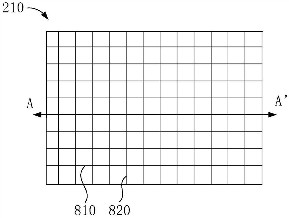
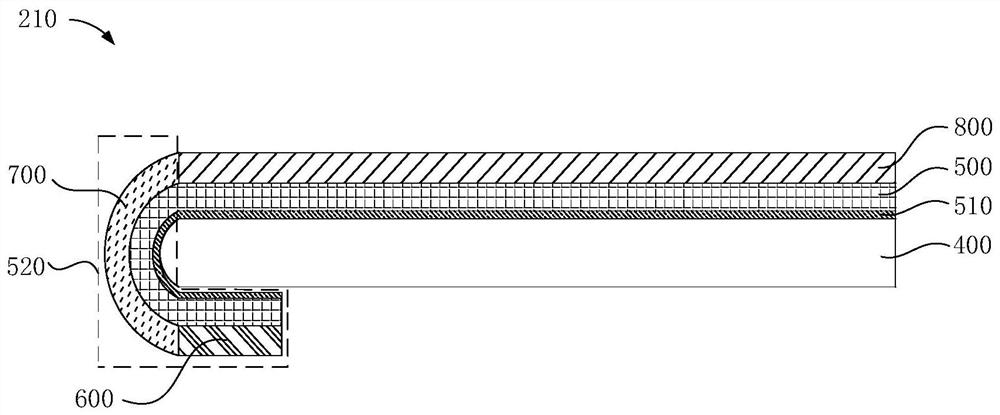
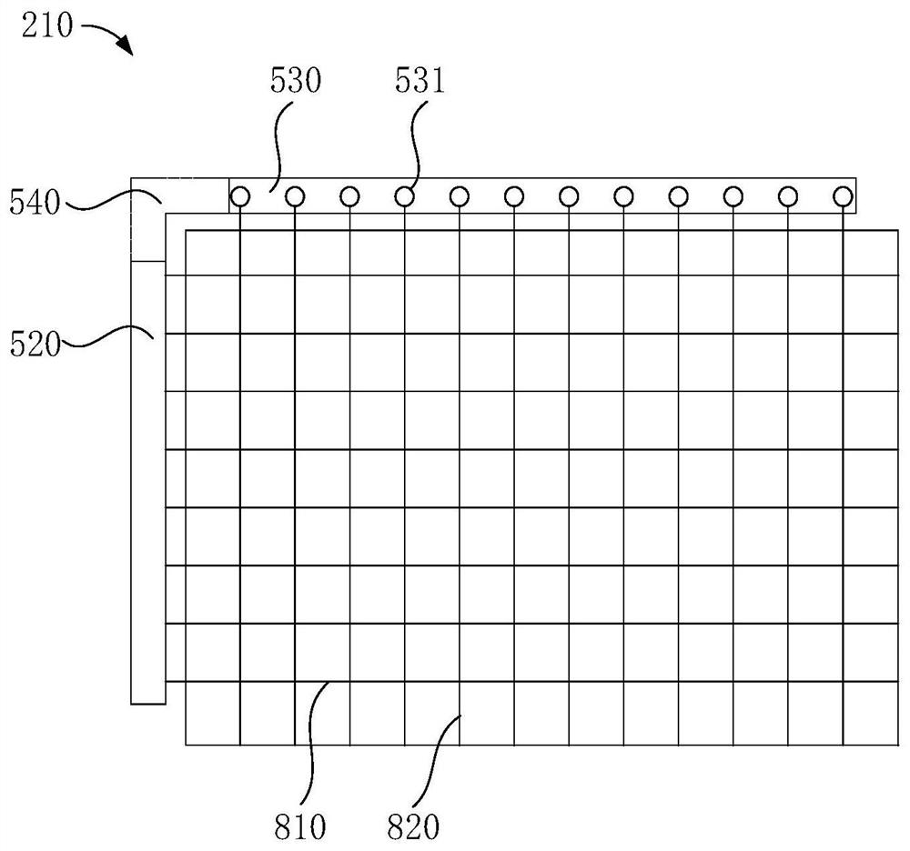

Image

  • Array substrate, display device and manufacturing method of display device
  • Array substrate, display device and manufacturing method of display device
  • Array substrate, display device and manufacturing method of display device

Examples


Embodiment Construction

[0042] It should be understood that the terminology and specific structural and functional details disclosed herein are representative only for describing specific embodiments, but the application can be embodied in many alternative forms and should not be construed as merely Be limited by the examples set forth herein.

[0043] In the description of the present application, the terms "first" and "second" are used for descriptive purposes only, and cannot be understood as indicating relative importance, or implicitly indicating the quantity of indicated technical features. Therefore, unless otherwise specified, the features defined as "first" and "second" may explicitly or implicitly include one or more of these features; "plurality" means two or more. The term "comprising" and any variations thereof mean non-exclusive inclusion, possible presence or addition of one or more other features, integers, steps, operations, units, components and / or combinations thereof.

[0044] Al...


PUM

PropertyMeasurementUnit
thicknessaaaaaaaaaa
thicknessaaaaaaaaaa

Abstract

The invention discloses an array substrate, a display device and a manufacturing method of the display device. The array substrate comprises a glass substrate, a flexible substrate, a display driving array, a plurality of signal lines and an array substrate row driving circuit, wherein the flexible substrate covers the first surface of the glass substrate, and one part of the flexible substrate protrudes out of the side edge of the glass substrate and is bent from the first surface of the glass substrate to the second surface of the glass substrate to form a bending area; the display driving array is arranged on one surface, far away from the glass substrate, of the flexible substrate; the plurality of signal lines correspond to the bending area and are arranged on the flexible substrate; and the array substrate row driving circuit corresponds to the bending area, is arranged on the flexible substrate and is connected with the display driving array through the plurality of signal lines. By means of the mode, the narrow-frame or frameless design is achieved.

Description

technical field [0001] The present application relates to the field of display technology, and in particular to an array substrate, a display device and a method for manufacturing the display device. Background technique [0002] For the panel industry, in order to meet the market demand, liquid crystal displays are also gradually becoming narrower, and further developing in the direction of no border. This narrow border or even borderless design can reduce the additional area of ​​the LCD to a certain extent, bringing people Better look and feel. [0003] The existing technology usually reduces the width of the frame by changing the layout of the gate drive circuit. On the array substrate, the array substrate row drive circuit is formed, and the row scan drive circuit is fabricated by the same process as the thin film transistor, which saves the integrated circuit part related to scan drive and realizes the reduction of the production cost of the liquid crystal display. Ho...

Claims


Application Information

Patent Timeline
Patent Type & Authority Applications(China)
IPC IPC(8): G02F1/1333G02F1/1345
CPCG02F1/133305G02F1/13452
Inventor 熊钦卢劲松孙松洪文进许哲豪陈政鸿袁海江
Owner BEIHAI HKC OPTOELECTRONICS TECH CO LTD
Why Eureka
Try Eureka