
Intelligent power distribution cabinet for preventing instrument lens from being atomized

A technology for instrumentation and power distribution cabinets, applied in substation/distribution device casings, electrical components, substation/switch layout details, etc. It can solve problems such as poor sealing and data reading, achieve a good limit effect, and speed up the flow rate. , good dustproof effect

Pending Publication Date: 2021-10-22
杨桂芳
View PDF0 Cites 0 Cited by
  • Summary
  • Abstract
  • Description
  • Claims
  • Application Information

AI Technical Summary

Problems solved by technology

[0004] Based on the technical problem that the interior of the existing power distribution cabinet is too humid due to poor sealing during the use of the existing power distribution cabinet, resulting in more water vapor adhering to the instrument lens and affecting the reading of data by the staff, the present invention proposes An intelligent power distribution cabinet that prevents fogging of instrumentation lenses

Method used


Image

  • Intelligent power distribution cabinet for preventing instrument lens from being atomized
  • Intelligent power distribution cabinet for preventing instrument lens from being atomized
  • Intelligent power distribution cabinet for preventing instrument lens from being atomized

Examples


Embodiment 1

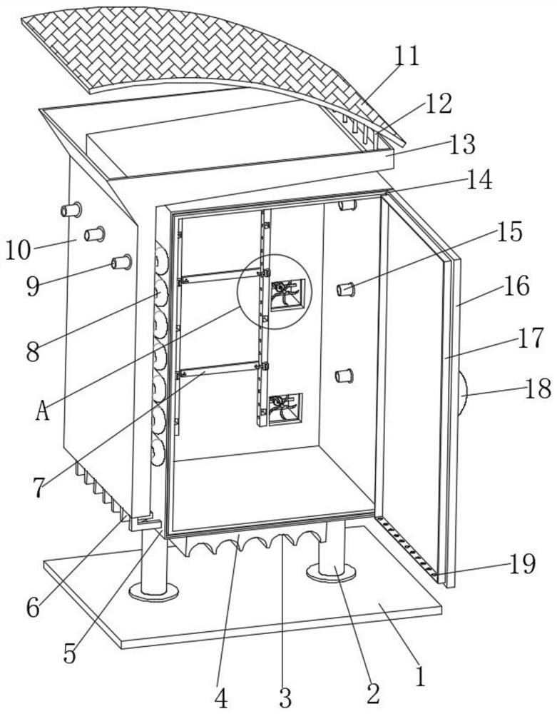
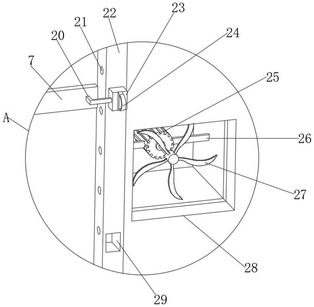
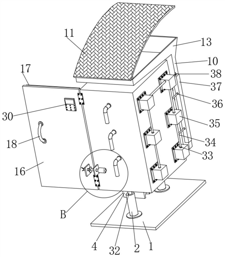
[0031] refer to Figure 1-6 , an intelligent power distribution cabinet for preventing fogging of instruments and meters, comprising a base plate 1, a cabinet body 5 and a control panel 30, one side of the cabinet body 5 is fixedly connected with a mounting plate 33, and one side of the mounting plate 33 is fixedly connected with a shell Body 35, one side of housing 35 is plugged with conduit 34, one side of conduit 34 is plugged with connecting pipe 36, one end of connecting pipe 36 is plugged with square pipe 37, and one side of square pipe 37 is plugged with equidistant Distributed suction bucket 53, one side inner wall of cabinet body 5 is provided with through groove 28, both sides inner wall of housing 35 is fixedly connected with second fixed rod 26, and one end of second fixed rod 26 is fixedly connected with motor 25, One end of the output shaft of the motor 25 is fixedly connected with a fan blade 27, and the inner wall of one side of the cabinet body 5 is fixedly co...

Embodiment 2

[0035] refer to Figure 7 , compared with Embodiment 1, this implementation also includes a spring 56 sleeved on the outer peripheral wall of the fixed column 44, and one end of the spring 56 is fixedly connected to one side of the outer wall of the limit plate 45, and the cabinet door 16 needs to be adjusted by the staff. During position-limiting work, it is necessary for the staff to twitch the fixed post 44 when opening the door and release it after the cabinet door 16 is opened. At this time, the spring 56 sleeved on the outer wall of the fixed post 44 recovers and deforms and the fixed post 44 is ejected into the positioning hole 43. Thereby finished the positioning work to cabinet door 16.


PUM


Abstract

The invention belongs to the technical field of power distribution cabinets, and particularly relates to an intelligent power distribution cabinet for preventing an instrument lens from being atomized. In order to solve the problem that data reading by workers is affected by more water vapor adhered to an instrument lens when the interior of an existing power distribution cabinet is too wet due to poor sealing performance in the using process of the existing power distribution cabinet, the following scheme is provided, namely, the intelligent power distribution cabinet comprises a bottom plate, a cabinet body and a control panel; one side of the cabinet body is fixedly connected with a mounting plate; one side of the mounting plate is fixedly connected with a shell; a guide pipe is inserted into one side of the shell; and a connecting pipe rod is inserted into one side of the guide pipe. By arranging a fan and an exhaust pipe, an instrument on a mounting frame can be uniformly dehumidified by cold air, so that the influence of water vapor generated on the lens of the instrument on the data reading work of a worker can be effectively avoided.

Description

technical field [0001] The invention relates to the technical field of power distribution cabinets, in particular to an intelligent power distribution cabinet for preventing fogging of instruments and meters. Background technique [0002] Power distribution cabinets are divided into power distribution cabinets, lighting distribution cabinets, and metering cabinets, and are the final equipment of the power distribution system. The power distribution cabinet is a general term for the motor control center. The power distribution cabinet is used in the occasions where the load is relatively scattered and there are few circuits; the motor control center is used in the occasions where the load is concentrated and there are many circuits. They distribute the electric energy of a certain circuit of the upper-level power distribution equipment to the nearest load. This level of equipment shall provide protection, monitoring and control of the load. [0003] During the use of the e...

Claims


Application Information

Patent Timeline
IPC IPC(8): H02B1/28H02B1/30H02B1/38H02B1/50H02B1/56
CPCH02B1/28H02B1/565H02B1/30H02B1/306H02B1/303H02B1/505H02B1/38
Inventor 杨桂芳
Owner 杨桂芳
Learn More