
Novel magnetic force safety type coupler

A coupler and safety technology, applied in the field of new magnetic safety couplers, can solve the problem that the magnetic coupler cannot be used alone, affects the normal operation of the magnetic coupler, and the use conditions of the magnetic coupler are high, so as to avoid excessive immersion depth. Large, reduce the impact, avoid the effect of excessive temperature

Active Publication Date: 2021-10-22
NANJING HUAMAI TECH
View PDF14 Cites 2 Cited by
  • Summary
  • Abstract
  • Description
  • Claims
  • Application Information

AI Technical Summary

Problems solved by technology

This solution can better dissipate the heat generated during the operation of the magnetic coupler and reduce the temperature rise during the operation of the magnetic coupler. However, during use, the magnetic coupler cannot be used alone and requires external equipment. support, so as to ensure the normal and orderly circulation of the cooling oil inside the magnetic coupler, and dissipate the heat quickly. The cooling oil in the magnetic coupler circulates, which may easily cause external impurities to enter the inside of the magnetic coupler, affecting the normal operation of the magnetic coupler

Method used


Image

  • Novel magnetic force safety type coupler
  • Novel magnetic force safety type coupler
  • Novel magnetic force safety type coupler

Examples


Embodiment approach

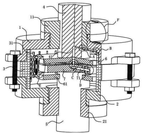
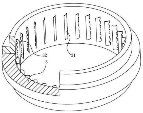
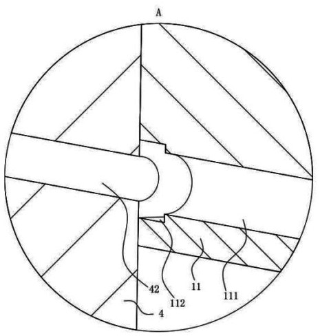
[0038] As an embodiment of the present invention, a transverse hole 71 is provided in the conductor disk 7, and the lateral hole 71 is distributed in the radial direction of the conductor disk 7; the lateral hole 71 has a plurality of, the centerline of the conductor disk 7 Uniform distribution; the lateral hole 71 is distingurated from the outlet of one end of the center of the conductor disc 7, and the diameter at the outlet is smaller than the diameter of the transverse hole 71; the conductor disk 7 is opened on the conductor disk 7; the connection hole 3 72; The centerline of the hole three 72 is coincident with the center line of the conductor disk 7, and the connection hole three 72 is turned on between the connecting hole 3 72 and the transverse hole 71; the magneto-disc 6 is fixed to the side surface of the conductor disk 7 is fixedly mounted 62 The outlet of the conduit 62 is positive to the connecting hole 3 72 on the conductor disk 7, and the end surface of the conduit ...


PUM


Abstract

The invention belongs to the technical field of magnetic couplers, and particularly relates to a novel magnetic force safety coupler, which comprises an upper mounting cover, a lower mounting cover and a movable ring, wherein the movable ring is positioned between the upper mounting cover and the lower mounting cover, the upper mounting cover, the lower mounting cover and the interior of the movable ring form a space I, an end cover I is fixedly mounted on the upper mounting cover, an end cover II is fixedly mounted on the lower mounting cover, an output shaft is rotationally mounted in the end cover I, an input shaft is rotationally mounted in the end cover II, a magnet disc I is fixedly mounted on the output shaft, the magnet disc I is fixedly provided with a magnet disc II through a fixing column, a through hole is formed in the middle position of the magnet disc, the input shaft enters the position between the magnet disc I and the magnet disc II from the through hole, a conductor disc is fixedly mounted on the input shaft, and the space I is filled with cooling oil. According to the invention, the structure is simple, the use condition is low, external equipment support is not needed, and the heat dissipation effect is good.

Description

Technical field [0001] The present invention belongs to the technical field of magnetic coupling, and is specifically a new magnetic safety coupler. Background technique [0002] The magnetic coupler is a device that achieves a torque transmission of the motor to the load by the air gap between the conductors and the permanent magnets, and the motor and the load-free transmission method can be achieved, and the working principle is when the two are relatively When exercising, the conductor assembly cuts the magnetores, generates a vorteur current in the conductor, and the eddy current is generated to generate an ink magnetic field, interact with the magnetic field generated by the permanent magnet, thereby achieving torque transfer between the two. The magnetic coupling is mainly composed of three parts of copper rotor, permanent magnet rotor, and controller. In general, the copper rotor is connected to the motor shaft, the shaft connection of the permanent magnet rotor and the w...

Claims


Application Information

Patent Timeline
Patent Type & Authority Applications(China)
IPC IPC(8): H02K49/04H02K49/10H02K9/19H02K5/20H02K5/18H02K5/24H02K5/10
CPCH02K49/046H02K49/102H02K9/19H02K5/203H02K5/18H02K5/24H02K5/10
Inventor 朱孟达李俊王峰
Owner NANJING HUAMAI TECH
Learn More