Supercharge Your Innovation With Domain-Expert AI Agents!

High-rise building deep foundation pit leaking stoppage drainage device

A technology for high-rise buildings and drainage devices, which is used in buildings, components of pumping devices for elastic fluids, infrastructure engineering, etc. Smooth, low-impact effects

Inactive Publication Date: 2021-10-26
祝佳卫
View PDF0 Cites 0 Cited by
  • Summary
  • Abstract
  • Description
  • Claims
  • Application Information

AI Technical Summary

Problems solved by technology

[0005] Aiming at the deficiencies of the prior art, the present invention provides a plugging and drainage device for deep foundation pits of high-rise buildings, which has the advantages of being able to monitor the drainage of the water pump, avoiding the damage of the water pump caused by the sediment in the water pump, and solving the problem of mud inhalation when the water pump is draining. The sand caused the blockage of the water inlet of the pump, and the staff could not deal with the problem of water pump drainage in time

Method used


Image

  • High-rise building deep foundation pit leaking stoppage drainage device
  • High-rise building deep foundation pit leaking stoppage drainage device
  • High-rise building deep foundation pit leaking stoppage drainage device

Examples


Embodiment 1

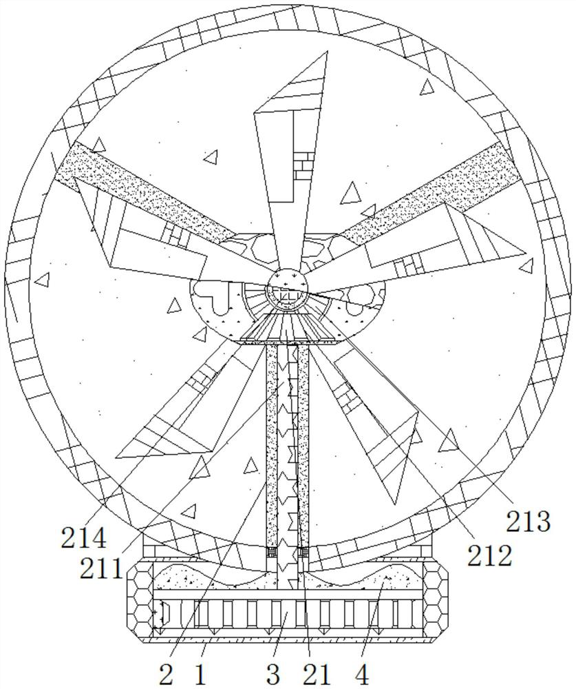
[0024] see Figure 1-3 , a plugging and drainage device for deep foundation pits of high-rise buildings, including a casing 1, a transmission mechanism 2 is movably connected to the inside of the casing 1, and the transmission mechanism 2 includes a power assembly 21 and a driven assembly 22, and the power assembly 21 is movably connected to the body of the casing 1. On the outside, the power assembly 21 includes a linkage rod 211, the linkage rod 211 is movably connected to the inside of the housing 1, the bevel gear 1 212 is fixedly connected to the outside of the linkage rod 211, the bevel gear 2 213 and the bevel gear 1 212 mesh, and the rotation rod 214 is movably connected to the outside of bevel gear 2 213, housing 215 is movably connected to the outside of linkage rod 211, rotating rod 214 is movably connected to housing 215, and fan blade 216 is fixedly connected to the outside of rotating rod 214.

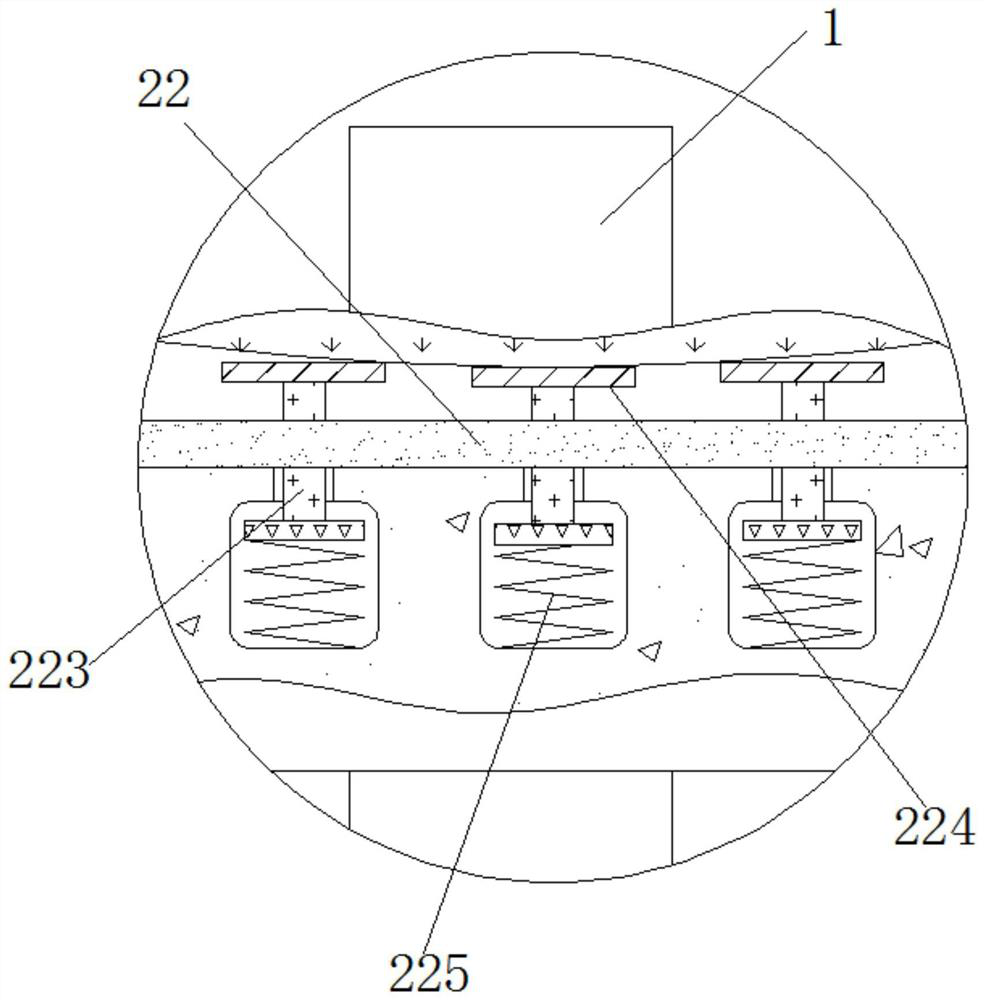
[0025] The driven assembly 22 is movably connected to the inner side...

Embodiment 2

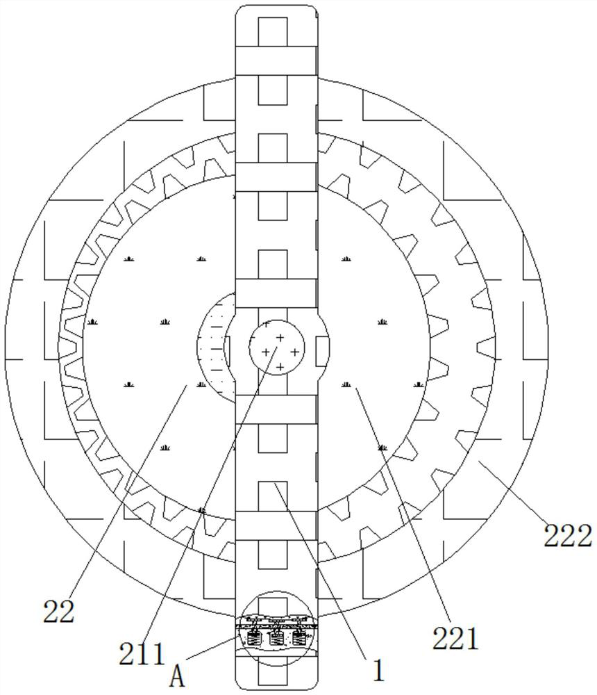
[0027] see Figure 4-5 , a plugging and drainage device for deep foundation pits of high-rise buildings, including a casing 1, and a transmission mechanism 2 is movably connected to the inside of the casing 1, and the transmission mechanism 2 includes a power assembly 21 that makes a driven assembly 22 move, so that the induction mechanism 3 controls the water flow rate. The driven assembly 22 for detection, the power assembly 21 is movably connected to the outside of the casing 1, the driven assembly 22 is movably connected to the inside of the casing 1, and the outside of the transmission mechanism 2 is movably connected to an induction mechanism 3, the induction mechanism 3 includes a turntable 31, Turntable 31 is fixedly connected to the outside of ring gear 222, and rotating rod 32 is movably connected to the inside of turntable 31, and limit bar 33 is movably connected to the inside of turntable 31, and spring 2 34 is movably connected to the outside of limit lever 33, an...

Embodiment 3

[0030] see Figure 1-5 , a plugging and drainage device for deep foundation pits of high-rise buildings, including a casing 1, a transmission mechanism 2 is movably connected to the inside of the casing 1, and the transmission mechanism 2 includes a power assembly 21 and a driven assembly 22, and the power assembly 21 is movably connected to the body of the casing 1. On the outside, the power assembly 21 includes a linkage rod 211, the linkage rod 211 is movably connected to the inside of the housing 1, the bevel gear 1 212 is fixedly connected to the outside of the linkage rod 211, the bevel gear 2 213 and the bevel gear 1 212 mesh, and the rotation rod 214 is movably connected to the outside of bevel gear 2 213, housing 215 is movably connected to the outside of linkage rod 211, rotating rod 214 and housing 215 are movably connected, and the outside of rotating rod 214 is fixedly connected with fan blade 216; driven assembly 22 The driven assembly 22 includes a gear 221 fixe...


PUM


Abstract

The invention relates to the technical field of deep foundation pit drainage, and discloses a high-rise building deep foundation pit leaking stoppage drainage device. The high-rise building deep foundation pit leaking stoppage drainage device comprises a shell, a transmission mechanism is movably connected to the interior of the shell and comprises a power assembly and a driven assembly, the power assembly is movably connected to the outer side of the shell, and the driven assembly is movably connected to the inner side of the shell. The outer side of the transmission mechanism is movably connected with an induction mechanism, and the inner side of the shell is fixedly connected with an external power source. Through meshing transmission of a gear and a gear ring, when a rotating disc normally drains water, a coil can be driven by a rotating rod to move, induction current is generated in a conductor, the position of an iron block is changed due to attraction of an electromagnet, and the water drainage condition of a water pump is judged; and meanwhile, due to buffering of a damping spring and an anti-collision pad, movement between the gear and the gear ring is more stable, and the influence of structural movement on water flow velocity detection is reduced.

Description

technical field [0001] The invention relates to the technical field of drainage of deep foundation pits, in particular to a plugging and drainage device for deep foundation pits of high-rise buildings. Background technique [0002] Foundation pit engineering mainly includes the design and construction of foundation pit support system and earthwork excavation, which is a highly comprehensive system engineering. It requires close collaboration between geotechnical and structural engineering technicians. [0003] When the foundation pit is excavated in the construction project, if the groundwater level is high and the base surface height is below the groundwater level, it needs to be dewatered to ensure the subsequent construction. When the foundation pit is drained, the water in the sump is due to the construction or the surrounding soil. Into the water, and then mixed with a lot of sediment in the water, it is easy to cause the water inlet of the pump to be blocked when pump...

Claims


Application Information

Patent Timeline
IPC IPC(8): F04D15/00F04D15/02F04D29/66G08B21/24E02D19/06E02D19/10
CPCF04D15/0088F04D15/0209F04D15/00F04D15/0077F04D29/669G08B21/24E02D19/06E02D19/10
Inventor 祝佳卫翁晓红
Owner 祝佳卫
Features
  • R&D
  • Intellectual Property
  • Life Sciences
  • Materials
  • Tech Scout
  • Unparalleled Data Quality
  • Higher Quality Content
  • 60% Fewer Hallucinations
Learn More