
Optical fiber curing oven

A technology of curing furnace and optical fiber, which is applied in the direction of light guide, optics, optical components, etc., can solve the problems such as the influence of optical fiber transmission, and achieve the effect of improving efficiency and applicability

Active Publication Date: 2021-10-26
SHENZHEN ADTEK TECH CO LTD
View PDF14 Cites 1 Cited by
  • Summary
  • Abstract
  • Description
  • Claims
  • Application Information

AI Technical Summary

Problems solved by technology

[0004] Regarding the above-mentioned related technologies, the inventor believes that due to the gap between the core and the cladding, the glue may flow along the core during the heating and curing process. Penetrates into the gap between the core and the cladding, thereby affecting the light transmission of the fiber

Method used


Image

  • Optical fiber curing oven
  • Optical fiber curing oven
  • Optical fiber curing oven

Examples


Embodiment 2

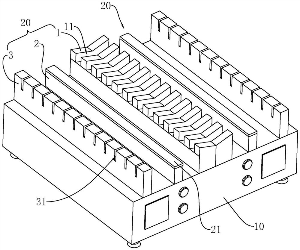
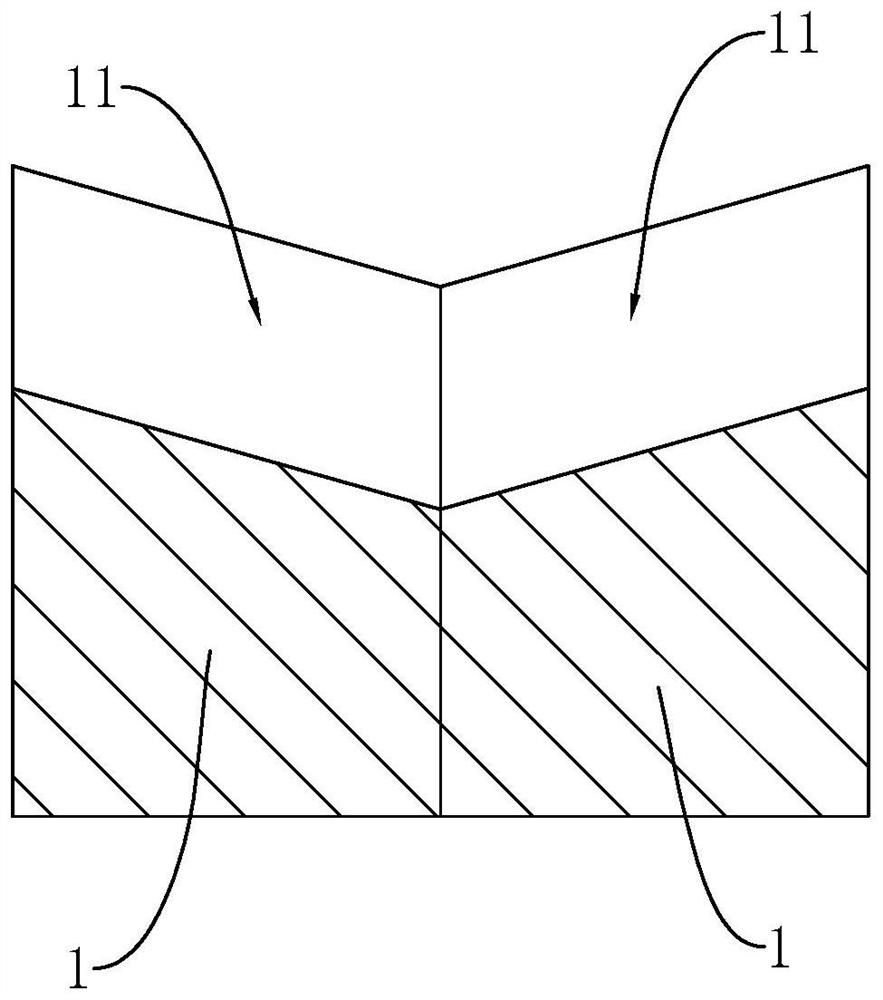
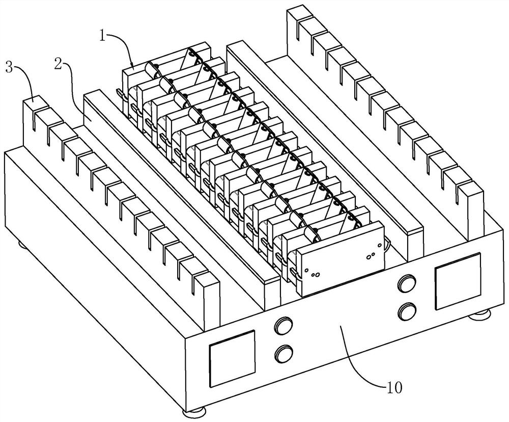
[0046] Embodiment 2, differs from embodiment 1 in that, as image 3 , Figure 4 As shown, the heating bar 1 includes a plurality of heating plates 12 arranged at intervals and a heating block 13 located between the two heating plates 12, wherein the heating plate 12 is fixedly connected with the heating furnace body 10, and the opposite sides of the heating block 13 are connected to the heating furnace body 10. The sides of the heating plate 12 are attached, and the heating structure 30 (heating wire or heating tube) on the heating furnace body 10 is connected to the heating plate 12 and the heating block 13 at the same time to heat the heating plate 12 and the heating block 13 .

[0047] like Figure 4 As shown, the upper surface of the heating block 13 and the side walls of the heating plates 12 on both sides form positioning grooves 11, the heating block 13 is a right-angle fan-shaped structure, and the right-angle edge of the heating block 13 is provided with rounded corn...


PUM


Abstract

The invention relates to an optical fiber curing oven which comprises a heating furnace body and a heating fixing assembly arranged on the heating furnace body. The heating fixing assembly comprises a heating strip and an elastic clamp which are arranged on the heating furnace body, the elastic clamp is used for clamping an optical fiber, and the heating strip is connected with a heating structure in the heating furnace body. The heating strip is provided with a positioning groove used for placing an optical fiber connector, the positioning groove is obliquely arranged, and one end, far away from the elastic clamp, of the positioning groove is lower than the other end of the positioning groove. According to the invention, the inclined positioning groove is arranged so that the position of the optical fiber connector on the inclined positioning groove is inclined downwards, and the glue on the optical fiber flows along the direction close to the optical fiber connector by using gravity so that the situation that the glue permeates into a gap between a fiber core and a cladding is effectively reduced.

Description

technical field [0001] The present application relates to the field of optical fiber processing equipment, in particular to an optical fiber curing furnace. Background technique [0002] The optical fiber has a cladding and a core located in the cladding. The end of the core of the optical fiber is connected to the optical fiber connector by means of glue bonding, and the rapid curing of the glue requires heating and curing in a fiber curing furnace. [0003] The specific heating and curing method is as follows: the optical fiber is fixed in the fixture, the to-be-heated part of the optical fiber is located in the positioning groove of the heating strip, and the optical fiber is heated and cured by the heat conduction of the heating strip. [0004] In view of the above-mentioned related technologies, the inventor believes that, due to the gap between the core and the cladding, during the heating and curing process, the glue may infiltrate into the gap between the core and th...

Claims


Application Information

Patent Timeline
Patent Type & Authority Applications(China)
IPC IPC(8): G02B6/255
CPCG02B6/2553
Inventor 马奎李宝荣余振龙
Owner SHENZHEN ADTEK TECH CO LTD
Learn More