
Optical fiber winding defect detection method and device based on ensemble learning

A defect detection and integrated learning technology, applied in image data processing, instrument, character and pattern recognition, etc., can solve problems such as misjudgment and missed detection, environmental interference and misdetection, difficult to locate accurately, etc. Environmental interference, high adaptability, and the effect of reducing frequent machine downtime

Active Publication Date: 2021-10-26
SHENZHEN GRADUATE SCHOOL TSINGHUA UNIV
View PDF17 Cites 2 Cited by
  • Summary
  • Abstract
  • Description
  • Claims
  • Application Information

AI Technical Summary

Problems solved by technology

This method has high algorithm complexity, large amount of data, and low real-time performance.
The requirements for shooting resolution are very high, and in the case of small fiber diameters, it is not easy to locate accurately, and it is easy to have misjudgments and missed detections. It is not suitable for solving problems at the industrial level.
CN105115981A discloses a method using edge straight line fitting and self-defined threshold to realize the defect detection of protrusions and depressions. It is difficult to capture clearly the edge of optical fiber with high rotational speed and small diameter, and the defect is not obvious and does not reach the self-defined threshold , the method is prone to missed detection, and the accuracy is not high enough
[0007] At present, various algorithms and defect detection systems have the problem that the theoretical significance is greater than the industrial application significance, and the algorithm complexity is high and the real-time performance is not high, and most of the algorithms have a lot of missed detection for inconspicuous defects, which will interfere with the environment. produce large false positives

Method used


Image

  • Optical fiber winding defect detection method and device based on ensemble learning
  • Optical fiber winding defect detection method and device based on ensemble learning
  • Optical fiber winding defect detection method and device based on ensemble learning

Examples


Embodiment Construction

[0049] Embodiments of the present invention will be described in detail below. It should be emphasized that the following description is only exemplary and not intended to limit the scope of the invention and its application.

[0050] The invention provides a method and system for detecting defects in optical fiber winding.

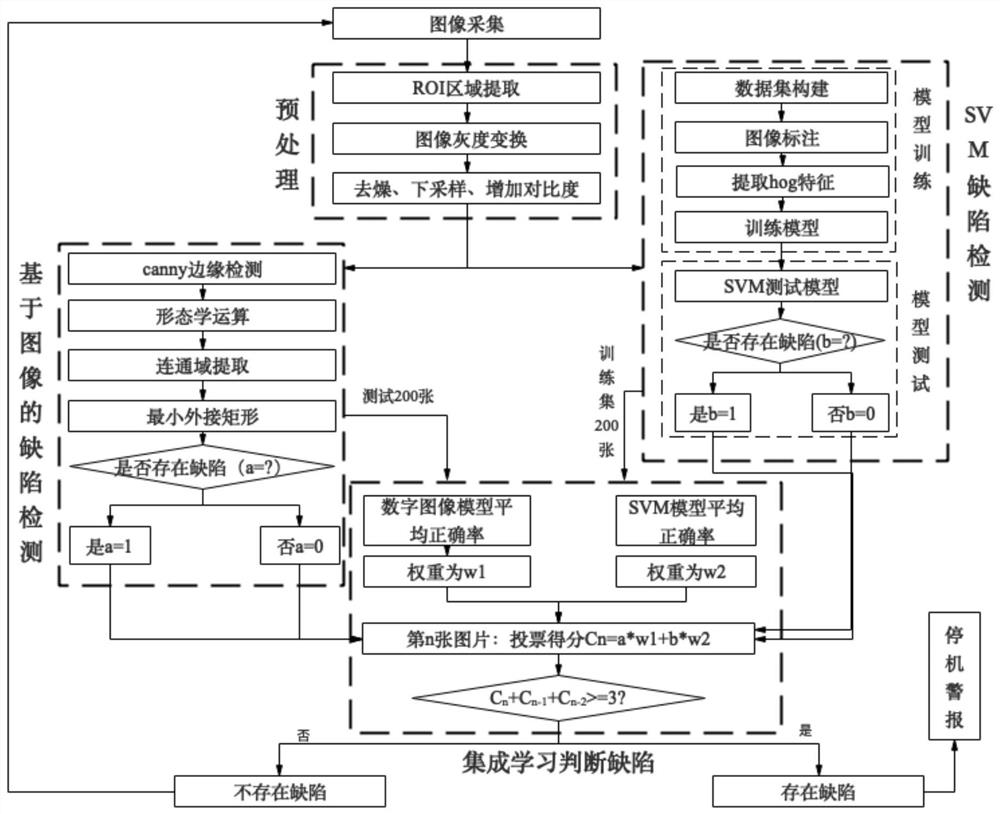
[0051] In some embodiments, a fully automatic optical fiber winding defect detection method includes a digital image processing algorithm part and an SVM learning algorithm part:

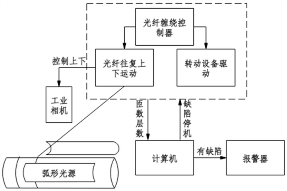
[0052] The first step: image collection, collecting industrial data images, intercepting the ROI (region of interest) area that has just been wrapped, and inputting it into the image preprocessing system.

[0053] The second step: image preprocessing. Perform preprocessing such as grayscale conversion, noise removal, image downsampling, and contrast increase on the collected images to lay the foundation for subsequent detection.

[0054] Step 3: Digital image processing to d...


PUM


Abstract

The invention discloses an optical fiber winding defect detection method and device based on ensemble learning. The method comprises the following steps of S1, acquiring an optical fiber winding image; S2, preprocessing the image acquired in the step S1; S3, carrying out defect detection on the image preprocessed in the S2 through a digital image processing model; S4, carrying out defect detection on the image preprocessed in the S2 through an SVM model; and S5, according to the digital image processing model and the SVM model, performing voting on defect detection results of the two models in the steps S3 and S4 according to corresponding weights by using a linear combination of set weight addition, judging whether voting results for a plurality of continuous pictures are not less than a set threshold score, and if so, judging that the optical fiber winding defect exists. The optical fiber winding defect detection device can reduce the misjudgment rate and the omission ratio, is suitable for optical fibers with various diameters, is more suitable for industrial environment production, and is high in adaptability.

Description

technical field [0001] The invention relates to an optical fiber winding defect detection technology, in particular to an optical fiber winding defect detection method and device based on integrated learning. Background technique [0002] Optical fiber guidance has been widely used in the military in recent years, and it is a key technology to deal with helicopters and tanks. Optical fiber guidance is the use of optical fiber sensing technology to realize real-time data transmission between ground consoles and air missiles. The principle of action is that there is a winding spindle-shaped optical fiber package at the tail of the missile connected to the launch console. The head of the missile is equipped with an infrared imaging reflection head or a low-light electronic camera. The picture is transmitted back to the ground in real time through optical fiber, and the shooter controls the missile according to the information transmitted back, and has the ability to launch, ob...

Claims


Application Information

Patent Timeline
Patent Type & Authority Applications(China)
IPC IPC(8): G06K9/62G06T7/00G06T7/13G06T7/136G06T7/155G06T7/181
CPCG06T7/0002G06T7/13G06T7/181G06T7/136G06T7/155G06F18/2411G06F18/214Y02P90/30
Inventor 曾龙欧雪燕冯平法谢颂强
Owner SHENZHEN GRADUATE SCHOOL TSINGHUA UNIV
Learn More