
Frequency modulation control circuit of resonant converter and control method thereof

A resonant converter and control circuit technology, applied in the control/regulation system, the conversion of AC power input to DC power output, the conversion of DC power input to DC power output, etc. Large step distance and other problems, to achieve the effect of good consistency, high phase accuracy, and cost reduction

Active Publication Date: 2021-10-26
SICHUAN INJET ELECTRIC CO LTD
View PDF9 Cites 2 Cited by
  • Summary
  • Abstract
  • Description
  • Claims
  • Application Information

AI Technical Summary

Problems solved by technology

[0004] The purpose of the present invention is to overcome the problems of large adjustment steps, poor adjustment accuracy, output adjustment and easy oscillation in the prior art, and provide a frequency modulation control circuit and control method for a resonant converter

Method used


Image

  • Frequency modulation control circuit of resonant converter and control method thereof
  • Frequency modulation control circuit of resonant converter and control method thereof
  • Frequency modulation control circuit of resonant converter and control method thereof

Examples


Embodiment 1

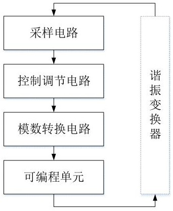
[0036] Such as figure 1 As shown, a frequency modulation control circuit of a resonant converter includes a sampling circuit, a control regulation circuit, an analog-to-digital conversion circuit and a programmable unit electrically connected in sequence.

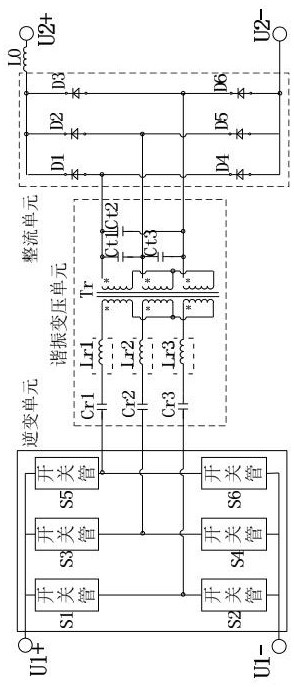
[0037] Such as figure 2 As shown, the resonant converter includes an inverter unit, a resonant transformer unit, and a rectifier unit that are electrically connected in sequence; specifically, the resonant converter is a three-phase high-frequency resonant converter, and the inverter unit includes a switching tube S1, Switch tube S2, switch tube S3, switch tube S4, switch tube S5, switch tube S6; the resonant transformer unit includes resonant capacitor Cr1, resonant capacitor Cr2, resonant capacitor Cr3, resonant capacitor Ct1, resonant capacitor Ct2, resonant capacitor Ct3 , a resonant inductor Lr1, a resonant inductor Lr2, a resonant inductor Lr3, a three-phase resonant transformer Tr; the rectifier unit includes a dio...

Embodiment 2

[0045] Such as Figure 5 As shown, the adjustment control circuit includes a conditioning circuit and a band resistance loop compensation circuit, the sampling circuit is an output current acquisition circuit, the conditioning circuit is a current loop conditioning circuit, the analog-to-digital conversion circuit is a voltage / frequency conversion circuit, and the reference signal is an output current The reference signal Iref controls the output of the three-phase resonant converter.

Embodiment 3

[0047] Such as Figure 6 As shown, the difference between this embodiment and Embodiment 2 is that the sampling circuit is an output voltage acquisition circuit, and the conditioning circuit is a voltage loop conditioning circuit.


PUM


Abstract

The invention relates to the field of circuit control, in particular to a frequency modulation control circuit of a resonant converter and a control method thereof. According to the invention, a sampling circuit, a control adjusting circuit, an analog-to-digital conversion circuit and a programmable unit are electrically connected in sequence, an electric signal output by the resonant converter is collected and is converted into the change of the corresponding driving signal, so as to control the output of the resonant converter. In other words, the excellent dynamic adjusting performance is achieved through analog adjustment in an analog and digital integrated control mode; meanwhile, the three-phase frequency modulation control signals output by the three-phase LCC resonant converter are good in consistency and high in phase precision, and the inter-phase self-current-sharing characteristic of the three-phase LCC resonant converter is good. Compared with an all-digital control method, a high-speed AD chip for signal acquisition is omitted, and the cost is greatly reduced.

Description

technical field [0001] The invention relates to the field of circuit control, in particular to a frequency modulation control circuit of a resonant converter and a control method thereof. Background technique [0002] At present, the resonant converter has the advantages of simple structure and can realize zero voltage switching (Zero Voltage Switch, ZVS for short). It adopts multi-phase interleaved parallel connection, which can not only increase the output power, but also reduce the input and output filters, among which The three-phase LCC resonant converter is one of its preferred topologies and is widely used in today's power supply designs. [0003] For the control of the three-phase resonant converter, in the prior art, high-speed AD acquisition chips are used together with DSP microprocessor for pure digital frequency modulation control, such as the existing patent CN201220396408.1 - a high-current high-frequency isolated DC-DC converter. Based on the development of ...

Claims


Application Information

Patent Timeline
Patent Type & Authority Applications(China)
IPC IPC(8): H02M3/335H02M7/5387H02M7/06H02M1/088
CPCH02M3/33569H02M3/33515H02M7/53873H02M7/066H02M1/088H02M1/083Y02B70/10
Inventor 赵奇龙君
Owner SICHUAN INJET ELECTRIC CO LTD
Learn More