Robot puncture positioning method and device for biliary tract puncture

A positioning method and technology of positioning device, which are applied to puncture needles, computer-aided surgery, computer-aided planning/modeling, etc., can solve the problems of low puncture positioning accuracy, and achieve the effect of reducing the number of needle penetrations and improving the accuracy.

Pending Publication Date: 2021-10-29
SHENZHEN INST OF ADVANCED TECH CHINESE ACAD OF SCI
View PDF0 Cites 0 Cited by
  • Summary
  • Abstract
  • Description
  • Claims
  • Application Information

AI Technical Summary

Problems solved by technology

[0008] The embodiment of the present invention provides a robot puncture positioning method and device for biliary tract

Method used


Image

  • Robot puncture positioning method and device for biliary tract puncture
  • Robot puncture positioning method and device for biliary tract puncture
  • Robot puncture positioning method and device for biliary tract puncture

Examples


Embodiment 1

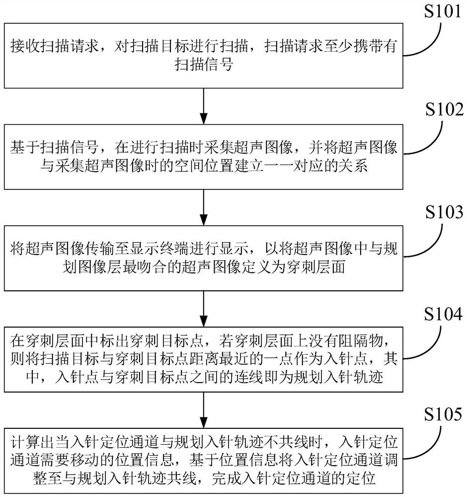
[0065] According to an embodiment of the present invention, a robot puncture positioning method for biliary tract puncture is provided, see figure 1 and figure 2 , including the following steps:

[0066] S101: Receive a scan request, and scan the scan target, where the scan request at least carries a scan signal;

[0067] S102: Based on the scan signal, acquire an ultrasound image during scanning, and establish a one-to-one correspondence between the ultrasound image and the spatial position when the ultrasound image is acquired;

[0068] S103: Transmitting the ultrasound image to the display terminal for display, so as to define the ultrasound image in the ultrasound image that is most consistent with the planned image layer as the puncture level;

[0069] S104: Mark the puncture target point on the puncture layer. If there is no barrier on the puncture layer, use the closest point between the scanning target and the puncture target point as the needle entry point, wherein...

Embodiment 2

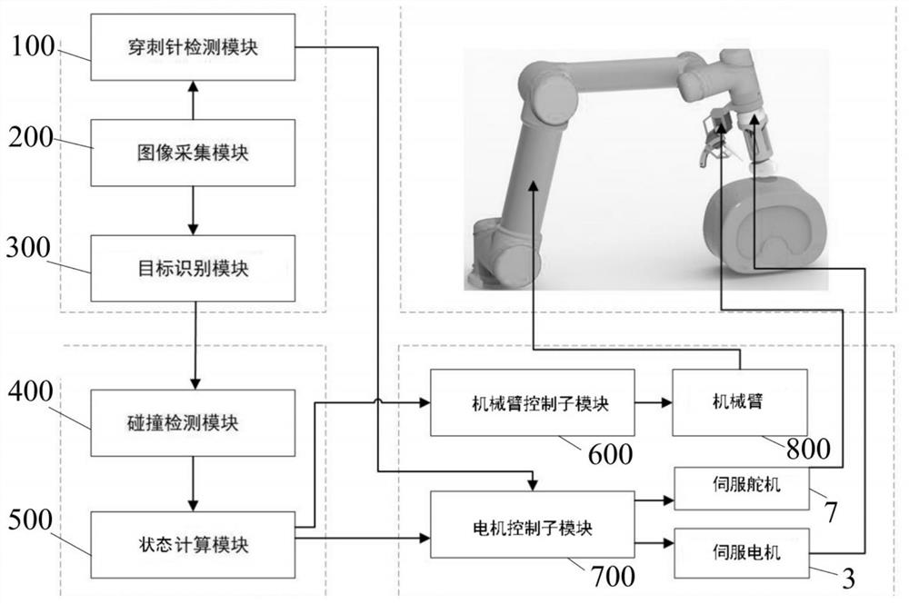
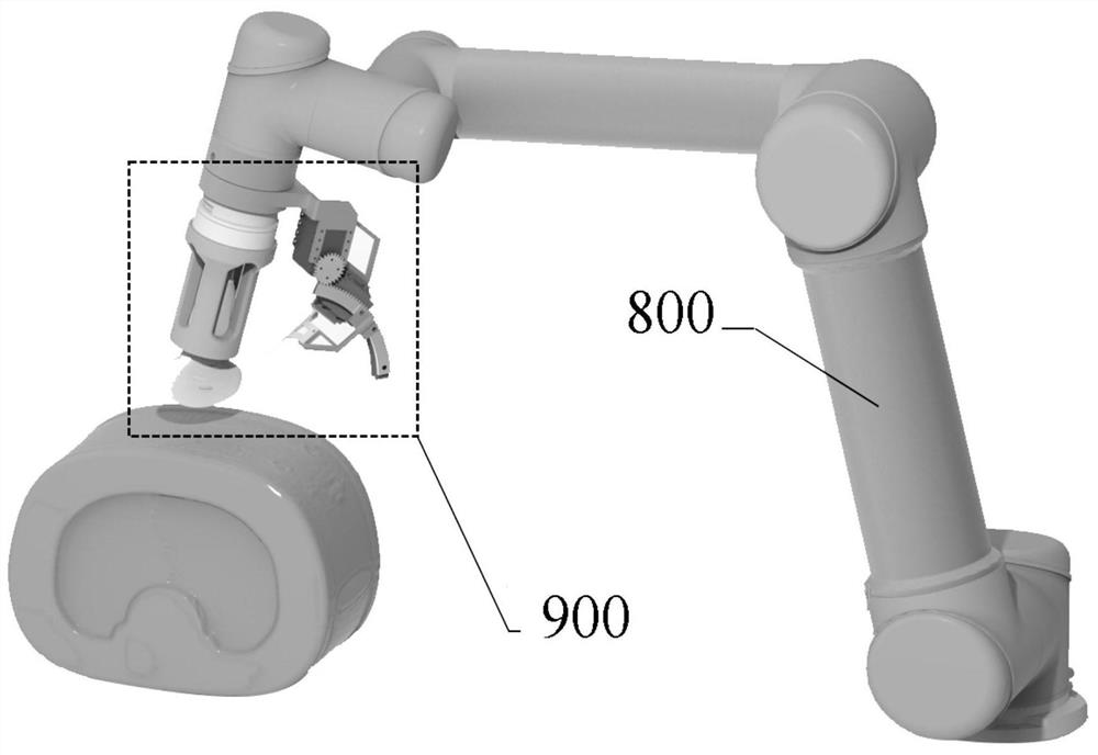
[0119] According to another embodiment of the present invention, a robot puncture positioning device for biliary puncture is provided, see Figure 2 to Figure 5 , including: a manipulator, an image acquisition module 200, a target recognition module 300, a collision detection module 400, a state calculation module 500 and a motion control module;

[0120] The motion control module is used to control the movement of the manipulator with six degrees of freedom, and controls the manipulator to scan the scanning target based on receiving the scanning request, and the scanning request carries at least a scanning signal;

[0121] The image acquisition module 200 is configured to acquire an ultrasonic image during scanning based on the scanning signal, and establish a one-to-one correspondence between the ultrasonic image and the spatial position when the ultrasonic image is acquired;

[0122] The target recognition module 300 is configured to transmit the ultrasound image to the dis...


PUM


Abstract

The invention relates to the field of intelligent medical equipment, in particular to a robot puncture positioning method and device for biliary tract puncture, and the method comprises the steps: receiving a scanning request, and scanning a scanning target; collecting ultrasonic images during scanning, and establishing a one-to-one correspondence relation between the ultrasonic images and the spatial positions when the ultrasonic images are collected; defining the ultrasonic image which is most matched with a planning image layer in the ultrasonic images as a puncture layer; if no barrier exists on the puncture layer, taking the point, closest to the puncture target point, of the scanning target as a needle entering point, and taking the connecting line between the needle entering point and the puncture target point as a planned needle entering track; and then, when a caculated needle entering positioning channel and the planned needle entering track are not collinear, adjusting the needle entering positioning channel to be collinear with the planned needle entering track, and completing positioning of the needle entering positioning channel. The robot puncture positioning method and device are used for positioning a puncture channel, the puncture positioning precision is improved, and the needle puncture frequency is reduced.

Description

technical field [0001] The invention relates to the field of intelligent medical equipment, in particular to a robot puncture positioning method and device for biliary tract puncture. Background technique [0002] Biliary interventional surgery is an important procedure in the treatment of biliary-related diseases such as cholangiography, internal and external biliary drainage, and malignant biliary obstruction. Whether the puncture operation can successfully penetrate into a specific part of the biliary tract is crucial to the entire treatment. Accurately hitting the planning target in the biliary tract means the smooth establishment of the interventional channel, and subsequent treatment methods including balloon dilatation catheters, dilatable stents, and radioactive particle stents can be carried out smoothly. Before the puncture operation, the doctor will plan the level of the puncture needle based on the patient's CT or MRI images. During puncture surgery, doctors nee...

Claims


Application Information

Patent Timeline
IPC IPC(8): A61B17/34A61B34/10
CPCA61B17/3403A61B34/10A61B2017/3413A61B2034/107
Inventor 陈静涛周寿军钱程曾泉林晓锋温铁祥
Owner SHENZHEN INST OF ADVANCED TECH CHINESE ACAD OF SCI
Why Eureka
Try Eureka