Supercharge Your Innovation With Domain-Expert AI Agents!

Gap compensation positioning device and method for fork-shaped part

A technology of gap compensation and positioning device, which is applied in workpiece clamping devices, metal processing, metal processing equipment, etc., can solve the problem of gap uniformity, low controllability of the fit on both sides, and coordination of the installation of the hinge mechanism. Large and fork-shaped parts have low center accuracy and other problems, so as to achieve the effects of convenient on-site management, high fitting accuracy and reliable compensation

Pending Publication Date: 2021-10-29
XI'AN AIRCRAFT INTERNATIONAL
View PDF5 Cites 0 Cited by
  • Summary
  • Abstract
  • Description
  • Claims
  • Application Information

AI Technical Summary

Problems solved by technology

However, in the actual operation process, the notches of different sorties of fork-shaped parts are larger than the theoretical notch size within the tolerance range, the lug positioner is smaller than the theoretical thickness of the lug within the tolerance range, and the clearance values ​​on both sides of the fork lugs of different sorties are also different. In addition, it is difficult and inefficient for workers to manually insert inserts. Therefore, in most cases, thinner, easy-to-insert inserts are selected for gap compensation. The accuracy of the center face is not high, and the fork-shaped parts are prone to be twisted, which has a great impact on the subsequent coordination and installation of the hinge mechanism.

Method used


Image

  • Gap compensation positioning device and method for fork-shaped part
  • Gap compensation positioning device and method for fork-shaped part
  • Gap compensation positioning device and method for fork-shaped part

Examples


Embodiment Construction

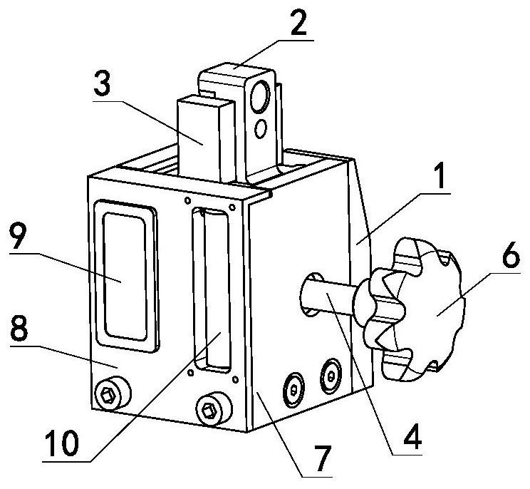
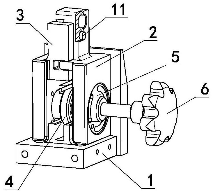
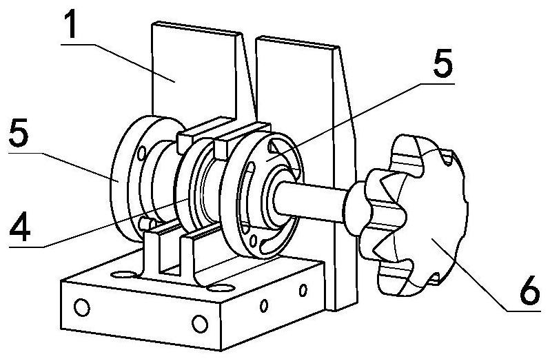
[0024] Reference attached Figure 1-6 As shown, a gap compensation positioning device for fork-shaped parts includes a base 1, a handle 6, an adjusting screw 4, a flange bush 5, positive positioning jaws 3, reverse positioning jaws 2, multiple end sensors 11, miniature Display 9, side baffle 7, front baffle 8. The base 1 is an L-shaped structure, with a vertical slot on both inner sides, the adjusting screw 4 is a stepped structure, the large circle in the middle is a chuck matching the vertical slot, and the flange bushing 5 is set on both ends of the adjusting screw 4 , the handle 6 is installed on the end of the adjusting screw 4, and the corresponding position on the forward / reverse positioning jaw 3 / 2 is provided with a pre-embedded hole of the end sensor 11, and a plurality of end sensors 11 are fixed in the pre-embedded hole, and the reverse positioning jaw 2 There are product positioning holes on it, the positive positioning jaw 3 and the reverse positioning jaw 2 are...


PUM


Abstract

The invention discloses a gap compensation positioning device and method for a fork-shaped part. The device comprises a base, a handle, an adjusting threaded rod, a flange bushing, a forward positioning clamping jaw, a reverse positioning clamping jaw, a plurality of tail end sensors, a micro display and a battery assembly. The tail end sensors are arranged on the forward / reverse positioning clamping jaw, a product positioning hole is formed in the reverse positioning clamping jaw, the forward positioning clamping jaw and the reverse positioning clamping jaw are used in cooperation, the fork-shaped part is arranged on a frame, a part notch and an upper fork lug structure formed after the forward / reverse positioning clamping jaws are combined are sleeved, and a positioning pin is inserted into a fork-shaped part intersection point hole and positioning holes in the forward / reverse positioning clamping jaws for hole-pin matching positioning. The handle on the adjusting threaded rod is rotated, and the forward / reverse positioning clamping jaws are driven by the flange lining to move and open at equal intervals in the reverse direction in the axial direction and are attached to the two inner side faces of the fork-shaped part. After the forward / reverse positioning clamping jaws are attached to the airplane fork-shaped part, the tail end sensors feed back a contact signal, and the contact state is displayed on the micro display.

Description

technical field [0001] The application relates to the technical field of aircraft assembly and manufacturing, in particular to a gap compensation positioning device and a compensation positioning method for fork-shaped parts. Background technique [0002] There are a large number of fork-shaped parts in the aircraft body structure, such as hatches, access covers, and the separation surface between the vertical tail and the fuselage of some models. Their common characteristics are many coordination features and high precision requirements, especially the multiple fork-shaped In the mechanism system where the parts work together, the centering requirement based on the center plane is directly related to the gap compensation ability of the hinge system installation and the flexibility of the axis movement function. [0003] The center surface of the traditional fork-shaped part is positioned by the lug locator. At least 1mm~2mm equidistant gap is left between the lug locator an...

Claims


Application Information

Patent Timeline
Patent Type & Authority Applications(China)
IPC IPC(8): B23P19/10B25B11/02
CPCB23P19/10B25B11/02
Inventor 李希王鸿昇周亮林金龙徐凯
Owner XI'AN AIRCRAFT INTERNATIONAL
Features
  • R&D
  • Intellectual Property
  • Life Sciences
  • Materials
  • Tech Scout
  • Unparalleled Data Quality
  • Higher Quality Content
  • 60% Fewer Hallucinations
Learn More