
Autonomous laying, recycling and charging device for AUV (Autonomous Underwater Vehicle) under severe sea conditions

A charging device and sea state technology, applied in circuit devices, electric vehicle charging technology, ship accessories, etc., can solve the problems of difficult and high-precision docking, easy damage, etc., and achieve the effect of reducing requirements and reducing the risk of collision

Active Publication Date: 2021-10-29
SHANGHAI JIAO TONG UNIV
View PDF0 Cites 5 Cited by
  • Summary
  • Abstract
  • Description
  • Claims
  • Application Information

AI Technical Summary

Problems solved by technology

First of all, the random dynamic changes of sea waves and currents will have complex effects on the horizontal and vertical position and heading of the AUV, and the wind, wave and current will have complex effects on the horizontal and vertical position and heading of the unmanned vehicle. As a result, it is difficult to perform high-precision docking between unmanned vehicles and AUVs, and the recovery method needs to leave as large a tolerance margin as possible for positioning deviations
Secondly, the recovery of AUV is limited by many factors. Since the ultra-short baseline system of AUV is installed on the bow, it is easily damaged by impact; the tail of a typical AUV has propellers in addition to the tail

Method used


Image

  • Autonomous laying, recycling and charging device for AUV (Autonomous Underwater Vehicle) under severe sea conditions
  • Autonomous laying, recycling and charging device for AUV (Autonomous Underwater Vehicle) under severe sea conditions
  • Autonomous laying, recycling and charging device for AUV (Autonomous Underwater Vehicle) under severe sea conditions

Examples


Embodiment

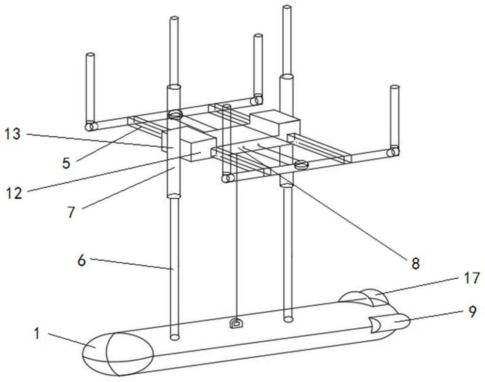
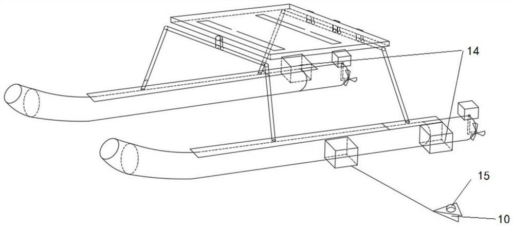
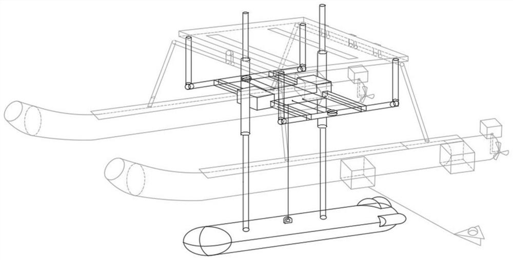
[0044] Such as figure 1 , figure 2 and image 3As shown, the present invention provides a device for autonomously and quickly deploying and recovering AUVs under harsh sea conditions. A more ideal effect can be obtained on the modular unmanned boat WAM-V. The recovered AUV is not allowed to have a dorsal fin, but a tail fin is allowed.

[0045] The device includes an elliptical cylinder capture cage 1, an AUV locking component 2, a wireless charging component 3, a wireless charging position identifier 4, a horizontal horizontal guide rail 5, a vertical rod 6, a stabilizing sleeve 7, a depth controller 8, and a main light group 9 , Underwater gliding wing 10, buffer pad 11, lateral movement controller 12, vertical rod locking clip 13, auxiliary light group 14, deployed side-view monitoring mechanism 15, AUV drive-in detector 16, fixed main camera 17, Lock the buckle 18 , the screw 19 and the wireless charging ring 20 .

[0046] The vertical rod 6 is made of high-strength a...


PUM


Abstract

The invention relates to an autonomous laying, recycling and charging device for an AUV (Autonomous Underwater Vehicle) under severe sea conditions. The device comprises an elliptic cylinder capturing cage, wherein the tail part of the elliptic cylinder capturing cage is opened, and an inner cavity is formed in the elliptic cylinder capturing cage; the device further comprises a capturing cage moving assembly which comprises a horizontal transverse guide rail erected at the bottom of an unmanned ship control platform and a steel cable winding and unwinding control mechanism which slides on the horizontal transverse guide rail to adjust the transverse position, and a capturing cage fixing assembly which comprises a vertical rod, a stable sleeve and a vertical rod locking clamp, the lower end of the vertical rod is fixedly connected with the elliptic cylinder capturing cage, the stable sleeve sleeves the vertical rod, the vertical rod locking clamp is fixedly connected with a steel cable winding and unwinding control mechanism; the device further comprises an AUV identification assembly which comprises an underwater lighting unit and an underwater visual sensor unit, and an AUV locking assembly which comprises a screw rod arranged in an inner cavity of the tail portion of the elliptic cylinder capturing cage and a locking buckle fixed to the screw rod. Compared with the prior art, the device has the advantages that the recoverable area is enlarged, the requirement for high-precision butt joint is lowered, and the collision risk of the bow portion during AUV recovery is lowered.

Description

technical field [0001] The invention relates to the field of autonomous underwater submersible recovery control, in particular to an AUV autonomous deployment recovery charging device under severe sea conditions. Background technique [0002] With the gradual progress of my country's ocean exploration and the continuous development of ocean technology, AUVs (autonomous underwater vehicles) are playing an increasingly important role in exploring the ocean and ensuring national security. Since the 21st century, marine scientific research, development and exploration engineering, and military applications have continuously put forward higher requirements for autonomous unmanned underwater vehicles. [0003] Although the working time and cruising range of AUVs under water are continuously improved, they are limited by the size of AUVs, the planning and layout of batteries, and the development of the battery industry itself. There are bound to be limits to optimizing AUV energy ...

Claims


Application Information

Patent Timeline
IPC IPC(8): B63B27/16B63C11/52H02J50/10H02J50/90
CPCB63B27/16B63C11/52H02J50/10H02J50/90B63B2027/165Y02T90/14
Inventor 张卫东金亦凡陈卫星朱翀杨子恒董博韬
Owner SHANGHAI JIAO TONG UNIV
Learn More