Construction method of jacking for large super-high and small radius circular curved steel box girder

A technology of jacking construction and steel box girder, applied in the direction of bridges, bridge construction, bridge materials, etc., can solve the problems of horizontal jacking method construction, complex force on the beam body, and unilateral voiding of the front fulcrum.

Active Publication Date: 2022-06-07
ROAD & BRIDGE INT +1
View PDF0 Cites 1 Cited by
  • Summary
  • Abstract
  • Description
  • Claims
  • Application Information

AI Technical Summary

Problems solved by technology

[0005] The main purpose of this application is to provide a method for jacking construction of large, super-high and small-radius circular curved steel box girders, so as to solve the effect of torsion and positive bending moment during the jacking construction of curved steel box girders in the related art, so that the beam body The stress becomes complicated, and the effect of torsion will produce a tendency of unilateral voiding of the front-end fulcrum or the adjacent front-end fulcrum, and due to the transverse and longitudinal slopes of the steel box girder, it cannot be constructed according to the conventional horizontal push-up method question

Method used


Image

  • Construction method of jacking for large super-high and small radius circular curved steel box girder
  • Construction method of jacking for large super-high and small radius circular curved steel box girder
  • Construction method of jacking for large super-high and small radius circular curved steel box girder

Examples


Embodiment Construction

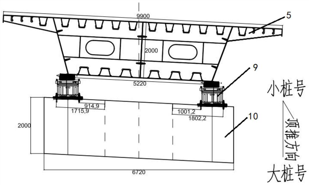
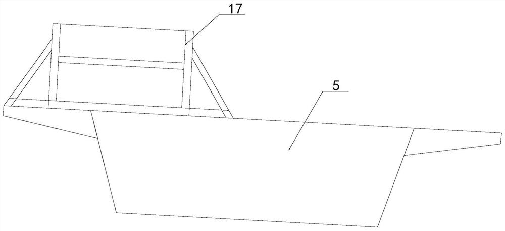
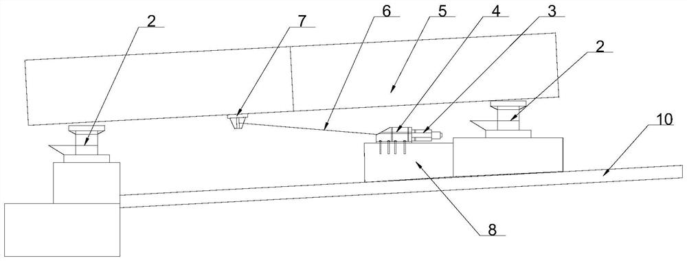
[0056] In order to make those skilled in the art better understand the solutions of the present application, the technical solutions in the embodiments of the present application will be clearly and completely described below with reference to the accompanying drawings in the embodiments of the present application. Obviously, the described embodiments are only The embodiments are part of the present application, but not all of the embodiments. Based on the embodiments in the present application, all other embodiments obtained by those of ordinary skill in the art without creative work shall fall within the scope of protection of the present application.

[0057] It should be noted that the terms "first", "second", etc. in the description and claims of the present application and the above drawings are used to distinguish similar objects, and are not necessarily used to describe a specific sequence or sequence. It is to be understood that the data so used are interchangeable un...


PUM


Abstract

This application discloses a construction method for jacking steel box girders with large, super-high and small radius circular curves, including the following steps: walking-type jacking equipment and temporary pad beam arrangement; steel box girders are assembled according to the transverse slope designed for the beam body Assembled with the longitudinal slope, the steel box girder is pushed to the temporary pad beam on the top of the adjacent cover beam by the jacking jack on the assembled tire frame and the walking-type jacking equipment on the top of the cover beam; the curved steel box girder is pushed ;Steel box girder deflection correction; steel box girder push counterweight, according to the section division of steel box girder, plan the walking distance of steel box girder and the cantilever length of steel box girder, and push the steel box girder each time According to the calculation results of the working conditions, the counterweight is adjusted for the existing negative reaction force working conditions and the unbalanced working conditions of the inner and outer sides of the steel box girder. The application achieves the purpose of overcoming the positive bending moment and torque effect of the cantilever state at the end of the box girder under the pushing state of the small-radius steel box girder, and ensuring that the pressure difference between the inner and outer pushing devices is within a certain range.

Description

technical field [0001] The present application relates to the technical field of steel box girder jacking construction, and in particular, to a jacking construction method of large, ultra-high, and small-radius circular curved steel box girder. Background technique [0002] During the jacking construction of steel box girder bridges with high piers in some mountainous areas, due to the terrain conditions of deep ditch in mountainous areas, there is no terrain condition for setting up temporary buttresses. high, the temporary piers become flexible, the horizontal stiffness is difficult to guarantee, and the resistance effectiveness of the vertical and horizontal forces during the jacking process is difficult to meet the requirements; and the bridge is located on an ultra-high line, the transverse and longitudinal slopes are large, and the top of the steel box girder is difficult to meet the requirements. When pushing, there is a risk of lateral and forward slippage. The probl...

Claims


Application Information

Patent Timeline
Patent Type & Authority Patents(China)
IPC IPC(8): E01D21/06E01D2/04E01D101/30
CPCE01D21/06E01D2/04E01D2101/30Y02A30/60
Inventor 刘慧田连民刘明强李腾达吴永生
Owner ROAD & BRIDGE INT
Why Eureka
Try Eureka