Geological and geotechnical investigation strength test sampling device

A technique of strength test and sampling device

Active Publication Date: 2021-10-29
杨柳
View PDF12 Cites 2 Cited by
  • Summary
  • Abstract
  • Description
  • Claims
  • Application Information

AI Technical Summary

Problems solved by technology

[0002] In the process of geotechnical investigation, soil drilling sampling is often used to sample soil and rock soil. Although the samples taken out can reflect the soil type and soil type of the current rock soil layer, soil drilling sampling will destroy The soil structure and the distribution of the material structure in the soil. At the same time, the soil needs to be cut during the soil drilling and sampling process. Such actions will cause the soil to receive additional extrusion and shearing forces, which will lead to the internal structure and stress of the soil. Changes are not conducive to understanding the initial state of the current internal structure of the rock and soil layer, and because the sample structure in the soil layer will be changed during the process of taking out the sample, and the overall structure cannot be taken out without stress. It can keep the soil in its original state after taking it out, so that the state of the current soil layer and the distribution of soil structure can be studied, so as to obtain accurate data

Method used


Image

  • Geological and geotechnical investigation strength test sampling device
  • Geological and geotechnical investigation strength test sampling device
  • Geological and geotechnical investigation strength test sampling device

Examples


Embodiment Construction

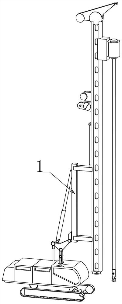
[0033] The following is attached Figure 1-14 The specific implementation manners of the present invention are further described in detail.

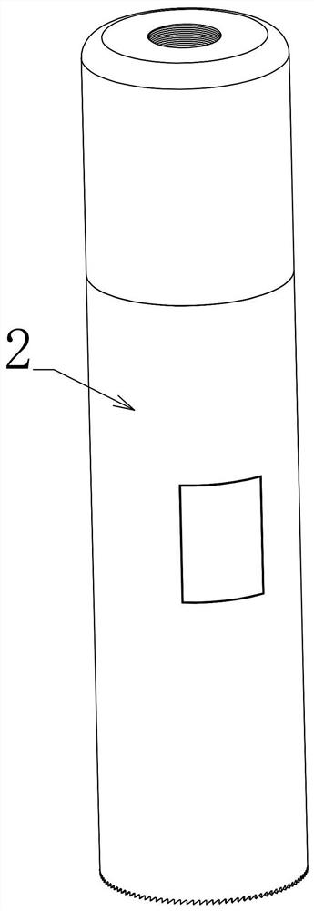
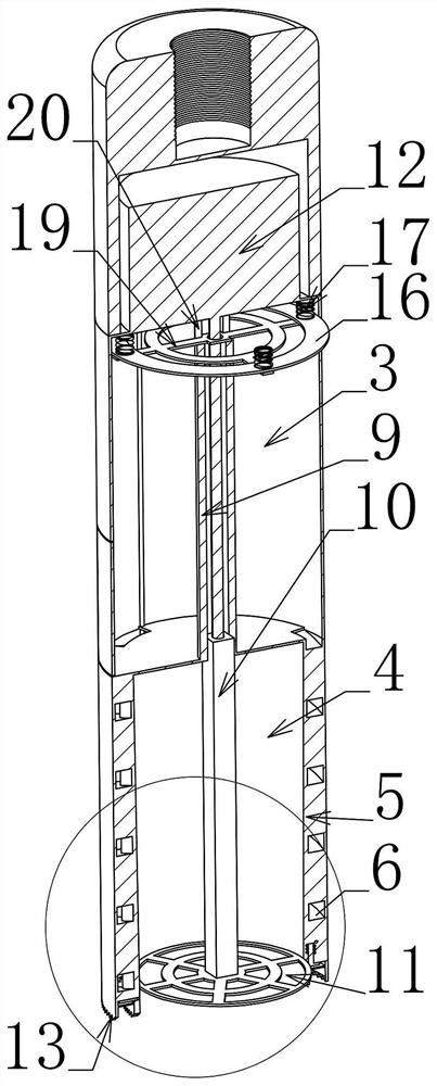
[0034] When this embodiment is in use, the sampling cylinder 2 is divided into upper and lower chambers, the upper chamber 3 is provided with a vertically arranged guide rod 9, the guide rod 9 is a hollow structure and the hollow part communicates with the lower chamber 4, The guide rod 9 is vertically slidably connected with a pressing rod 10, the upper end of the pressing rod 10 is driven up and down by the drive motor 12 fixedly connected to the upper chamber 3, and the lower end of the pressing rod 10 is fixedly connected with a pressing plate 11, which is It is vertically slidingly connected with the inner contour of the sampling cylinder 2. The lower part of the lower chamber is provided with a cutting layer 5, and a plurality of cutting teeth 8 are rotatably connected to the cutting layer 5. When each cutting tooth 8 is extended, ...


PUM


Abstract

According to a geological and geotechnical investigation strength test sampling device provided by the invention, a soil sample can be completely taken out under the condition that the soil sample is not crushed, and meanwhile, the structure of the taken-out soil is not changed, and additional internal stress does not exist, and therefore, the taken sample can accurately reflect the actual condition in the current soil layer; and according to the technical scheme, the sampling device comprises a drilling machine and is characterized by further comprising a sampler installed on the drilling machine, the sampler comprises a sampling barrel, the sampling barrel is divided into an upper cavity and a lower cavity through a partition plate, a cutting layer is coaxially and fixedly connected to the inner side wall of the lower cavity, cutting edges are arranged at the lower ends of the cutting layer and the spiral channel, a guide rod which is coaxially arranged is fixedly connected into the upper cavity, a pressing rod is vertically connected into the guide rod in a sliding mode, the lower end of the pressing rod downwards extends into the lower cavity, a vertically-arranged threaded hole is formed in the upper end of the pressing rod, and a pressing disc is arranged at the lower end of the pressing rod.

Description

technical field [0001] The invention relates to a geotechnical survey device, in particular to a geological geotechnical survey intensity test sampling device. Background technique [0002] In the process of geotechnical investigation, soil drilling sampling is often used to sample soil and rock soil. Although the samples taken out can reflect the soil type and soil type of the current rock soil layer, soil drilling sampling will destroy The soil structure and the distribution of the material structure in the soil. At the same time, the soil needs to be cut during the soil drilling and sampling process. Such actions will cause the soil to receive additional extrusion and shearing forces, which will lead to the internal structure and stress of the soil. Changes are not conducive to understanding the initial state of the current internal structure of the rock and soil layer, and because the sample structure in the soil layer will be changed during the process of taking out the...

Claims


Application Information

Patent Timeline
Patent Type & Authority Applications(China)
IPC IPC(8): G01N1/08G01N3/02
CPCG01N1/08G01N3/02G01N2203/0266Y02A90/30
Inventor 杨柳常晓蕾
Owner 杨柳
Why Eureka
Try Eureka