Positioning transfer device

A transfer device and positioning mechanism technology, applied in assembly machines, metal processing equipment, manufacturing tools, etc., can solve the problems of large space occupied by the positioning transfer device, winding of outgoing lines, heavy weight, etc., to reduce equipment capital investment, The effect of preventing wire entanglement and simplifying the structure

Pending Publication Date: 2021-11-02
BOZHON PRECISION IND TECH CO LTD
View PDF10 Cites 0 Cited by
  • Summary
  • Abstract
  • Description
  • Claims
  • Application Information

AI Technical Summary

Problems solved by technology

The active clamping power equipment in the prior art is installed on the transition support plate, which not only requires a large investment of equipment funds, but also the positioning and loading device takes up a lot of space, is heavy, and is easy to wind up the outgoing line.

Method used


Image

  • Positioning transfer device
  • Positioning transfer device

Examples


Embodiment 1

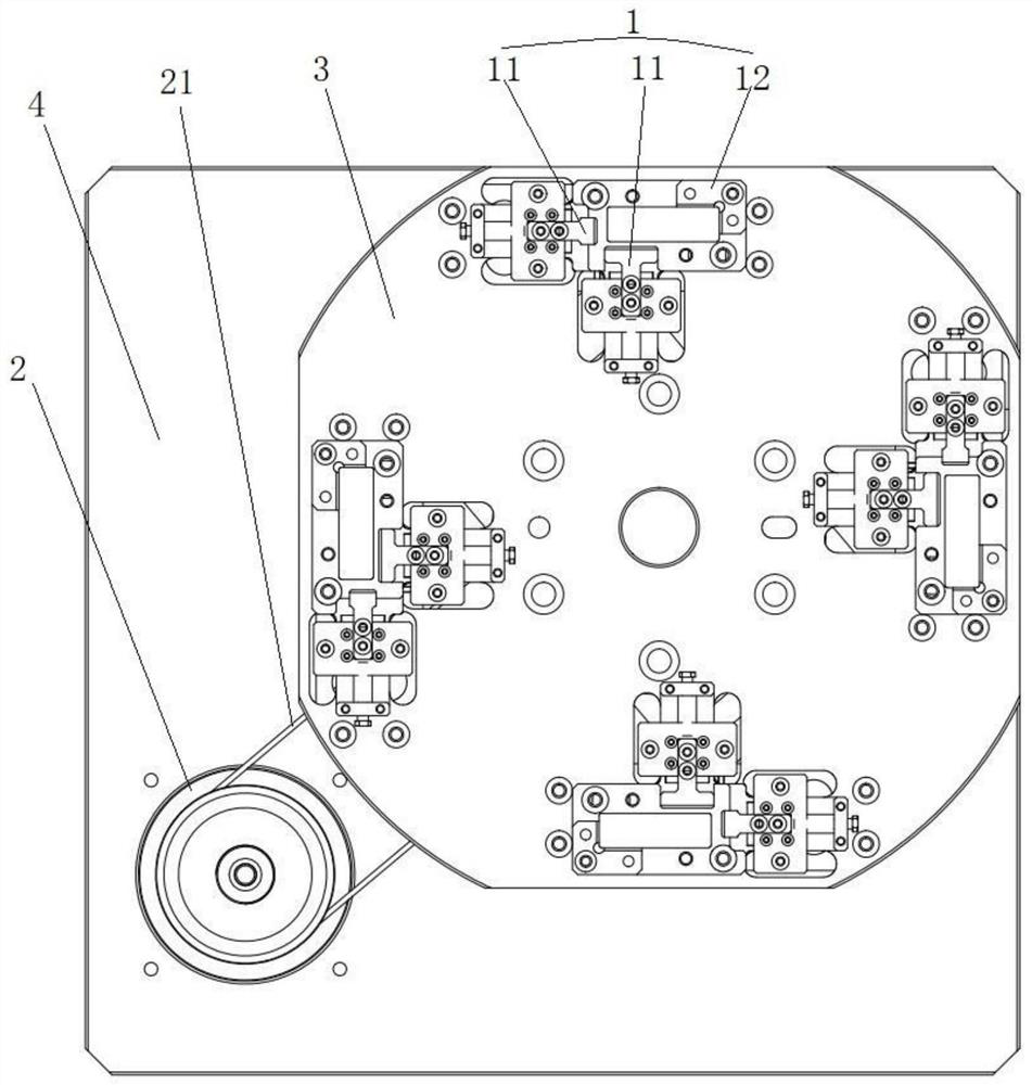
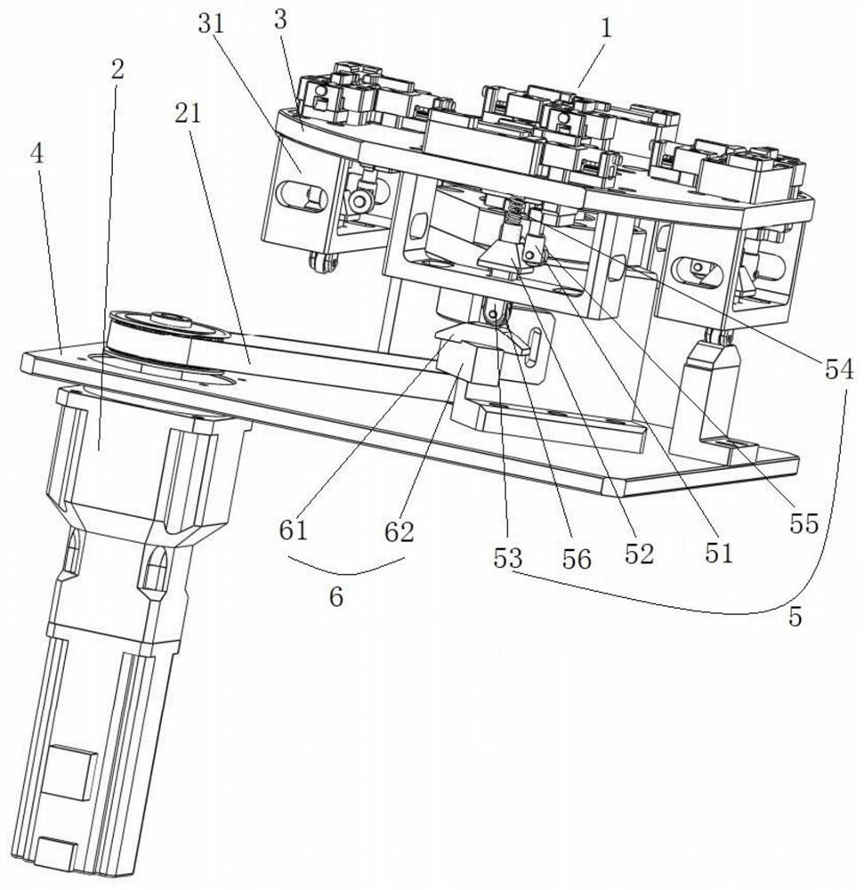
[0035] see figure 1 and figure 2 , as shown in the legend therein, a positioning transfer device includes a positioning mechanism 1 for positioning products and a power device 2 for driving the positioning mechanism 1 through the loading and unloading stations and non-loading and unloading stations. The positioning mechanism 1 Installed on a transition support plate 3, the transition support plate 3 is connected to the power output end of the power equipment 2, the fuselage of the power equipment 2 is installed on a fixed frame 4, and the positioning mechanism 1 includes movable activities relative to the transition support plate 3 The clamping block 11 and the clamping reset part (not shown in the figure) that drive the movable clamping block 11 to clamp the product,

[0036] The positioning mechanism 1 is correspondingly provided with a first linkage mechanism 5 for moving the movable clamping block 11, and a second linkage mechanism 6 for cooperating with the first linkag...


PUM


Abstract

The invention discloses a positioning transfer device. The device comprises a positioning mechanism, a transition supporting plate, a power device and a fixing rack, the positioning mechanism comprises a movable clamping block and a clamping reset component, and the positioning mechanism is correspondingly provided with a first linkage mechanism used for being in linkage with the movable clamping block to move. A second linkage mechanism used in cooperation with the first linkage mechanism is correspondingly installed on the fixing rack, and when the transition supporting plate drives the first linkage mechanism to pass through the second linkage mechanism, the second linkage mechanism makes contact with the first linkage mechanism passing through the second linkage mechanism to form a cam mechanism. The cam mechanism transmits the moving action of the transition supporting plate to the movable clamping block and drives the movable clamping block to move to the position where a product is loosened, and when the transition supporting plate drives the first linkage mechanism to leave the second linkage mechanism, the movable clamping block moves to the position where the product is clamped under the action of the reset force of the clamping reset component. According to the device, the movable clamping block does not need to be independently provided with driving equipment, the structure is ingenious, simple and practical, and the equipment cost is reduced.

Description

technical field [0001] The invention belongs to the technical field of positioning and transferring of products, and in particular relates to a positioning and transferring device. Background technique [0002] The information disclosed in this background section is only intended to enhance the understanding of the general background of the present invention, and should not be considered as an acknowledgment or any form of suggestion that the information constitutes the prior art that is already known to those skilled in the art. [0003] With the development of society, the increase of labor costs and the rise of the automation industry, the widespread use of automation equipment has become an irreplaceable trend. In the process of product assembly or testing, sometimes it is necessary to transfer the product to the standard operating position for the next step of processing, and the product needs to be clamped. At this time, a positioning and transferring device is needed....

Claims


Application Information

Patent Timeline
Patent Type & Authority Applications(China)
IPC IPC(8): B23P21/00
CPCB23P21/006
Inventor 杜祥哲刘武雷刘治渊
Owner BOZHON PRECISION IND TECH CO LTD
Why Eureka
Try Eureka