Rear bumper with EPP buffer block
A buffer block and bumper technology, which is applied in the field of bumpers, can solve problems such as poor bumper anti-collision buffering effects, and achieve the effect of avoiding serial car accidents and improving safety
- Summary
- Abstract
- Description
- Claims
- Application Information
AI Technical Summary
Problems solved by technology
Method used
Image
Examples
Embodiment 1
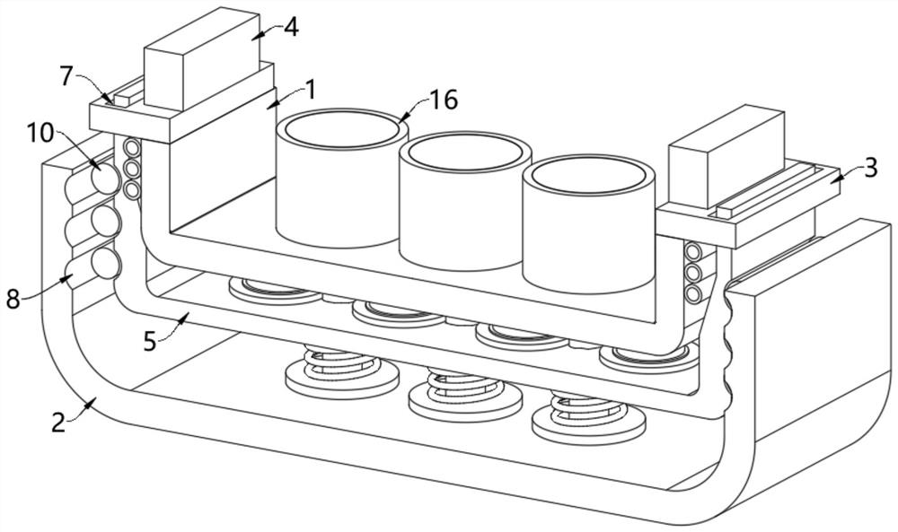
[0045] see figure 1 , figure 2 , Figure 4 with Figure 5 , the rear bumper with EPP buffer block, including a U-shaped reinforcing beam 1, the left and right ends of the U-shaped reinforcing beam 1 top are fixed with positioning plates 3, and the tops of the two positioning plates 3 pass through The crushing beam 4 is fixedly connected with the rear end of the car body, and when the vehicle has a very serious collision, the crushing of the crushing beam 4 can buffer part of the impact force;
[0046] The bottom of the reinforcement beam 1 is fixedly connected with a buffer interlayer 5 through a buffer block 13, and the rear cover 2 of an arched shape is movable below the buffer interlayer 5. In the present embodiment, the buffer block 13 is made of EPP material, and EPP (foaming poly Acrylic) material has the advantages of light specific gravity, good elasticity, shock resistance and compression resistance, high deformation recovery rate, good absorption performance, oil...
Embodiment 2
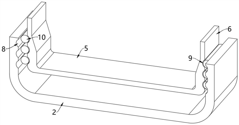
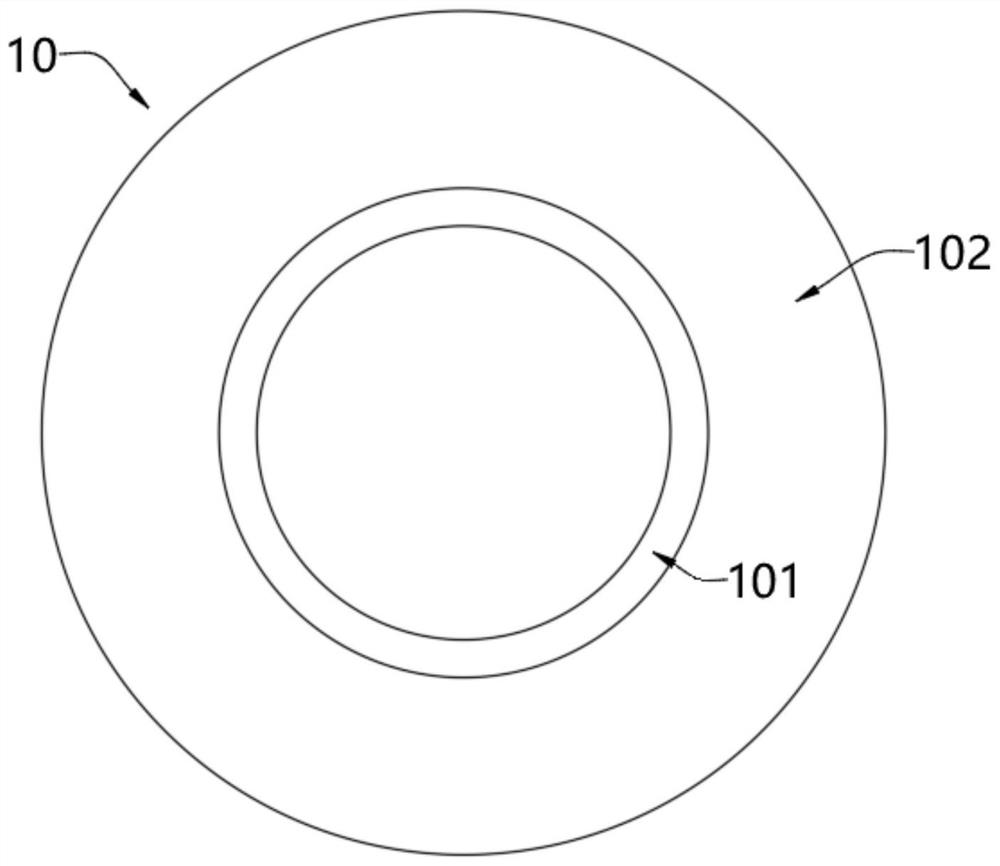
[0053] see image 3 with Image 6 , on the basis of Embodiment 1, the buffer column 10 includes a hollow cylinder 101 and a buffer sleeve 102 wrapped on the outer wall of the hollow cylinder 101. The buffer sleeve 102 is made of EPP material and is glued to the first arc groove 8 and the second arc groove. On the inner wall of the shaped groove 9, the interior of the hollow cylinder 101 stores colored gas, and the outer wall of the buffer sleeve 102 is evenly provided with vent holes;
[0054] When the vehicle is rear-end collided, the rear cover 2 moves toward the reinforcement beam 1 under the impact force of the rear vehicle, and when the rear cover 2 moves toward the reinforcement beam 1, the first arc-shaped groove 8 and the second arc-shaped groove The positions of 9 are mutually staggered, and at this time, the buffer column 10 bonded on the inner wall of the first arc-shaped groove 8 and the second arc-shaped groove 9 will be extruded and deformed from the first arc-s...
Embodiment 3
[0059] see Figure 7-Figure 10 On the basis of Embodiment 1 and Embodiment 2, storage tanks 16 are evenly arranged on the top of the reinforcement beam 1, fragile glass slides 17 are arranged on the top of the storage tank 16, and pistons 18 are movably arranged on the inner wall of the storage tank 16, A flame retardant is filled between the piston 18 and the fragile glass 17. In this embodiment, the flame retardant can be either nitrogen or carbon dioxide, which can reduce the oxygen concentration around the vehicle and also lower the temperature around the vehicle. ;
[0060] The bottom of the piston 18 is fixedly installed with a push rod 19, and the bottom end of the push rod 19 passes through the storage tank 16, the reinforcing beam 1 and the buffer interlayer 5 and is fixedly connected with a connecting plate 20, which is detachably and fixedly installed on the rear cover on the outer wall of 2;
[0061] When the vehicle is collided by a rear-end collision, the rear ...
PUM
 Abstract
Description
Claims
Application Information
 - R&D
- Intellectual Property
- Life Sciences
- Materials
- Tech Scout
- Unparalleled Data Quality
- Higher Quality Content
- 60% Fewer Hallucinations
Browse by: Latest US Patents, China's latest patents, Technical Efficacy Thesaurus, Application Domain, Technology Topic, Popular Technical Reports.
© 2025 PatSnap. All rights reserved.Legal|Privacy policy|Modern Slavery Act Transparency Statement|Sitemap|About US| Contact US: help@patsnap.com


