
Steel structure for concrete reinforcement

A concrete reinforcement and concrete structure technology, applied in building construction, building maintenance, construction, etc., can solve the problems of reduced service life of concrete beams, cracking of concrete beams, loss of building support, etc.

Pending Publication Date: 2021-11-02
NORTH CHINA UNIV OF WATER RESOURCES & ELECTRIC POWER
View PDF1 Cites 0 Cited by
  • Summary
  • Abstract
  • Description
  • Claims
  • Application Information

AI Technical Summary

Problems solved by technology

[0003] Concrete beam is an important part of the concrete structure of the building. During the long-term use of the concrete beam, in the process of bearing a large load, the concrete beam will appear bending deformation, and the concrete beam with increased deformation will Cracking occurs, and even the supporting effect on the building will be lost, and the service life of the concrete beam will be reduced. When the concrete beam is subjected to the load from top to bottom, the concrete is stressed in the way of compression on the upper part and tension on the lower part. Publication No. For CN103603509B's "Reinforced Concrete Beams Reinforced with Carbon Fiber Sheets and Its Reinforcement Method", the method of strengthening with carbon fiber sheets can improve the tensile capacity of reinforced concrete beams, but it cannot reduce the impact of compression on the upper part of reinforced concrete beams, and there is a reinforcement effect of concrete beams not strong problem

Method used


Image

  • Steel structure for concrete reinforcement
  • Steel structure for concrete reinforcement
  • Steel structure for concrete reinforcement

Examples


Embodiment Construction

[0031] The present invention will be further described below in conjunction with accompanying drawing and specific embodiment:

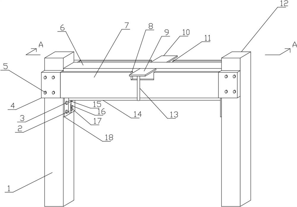
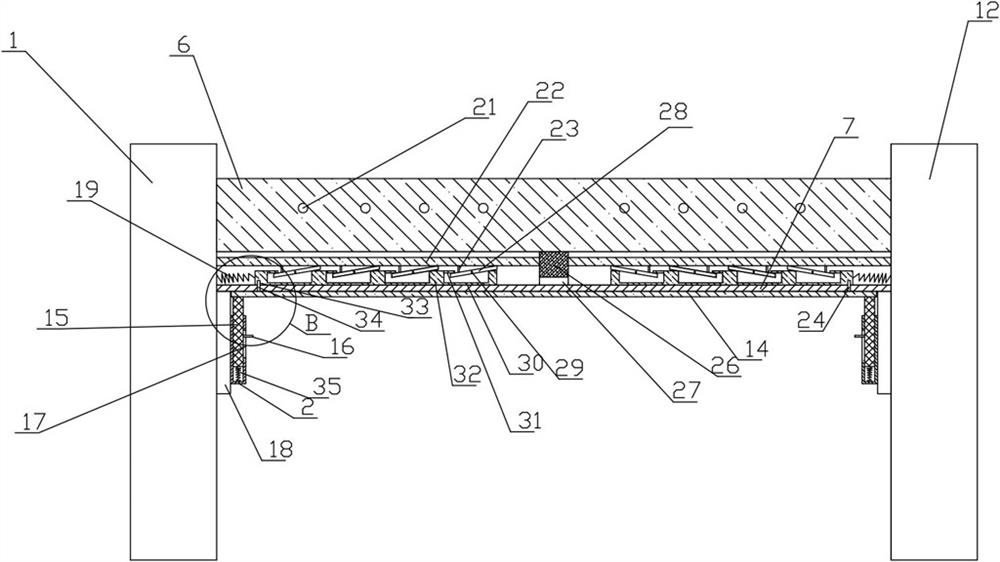
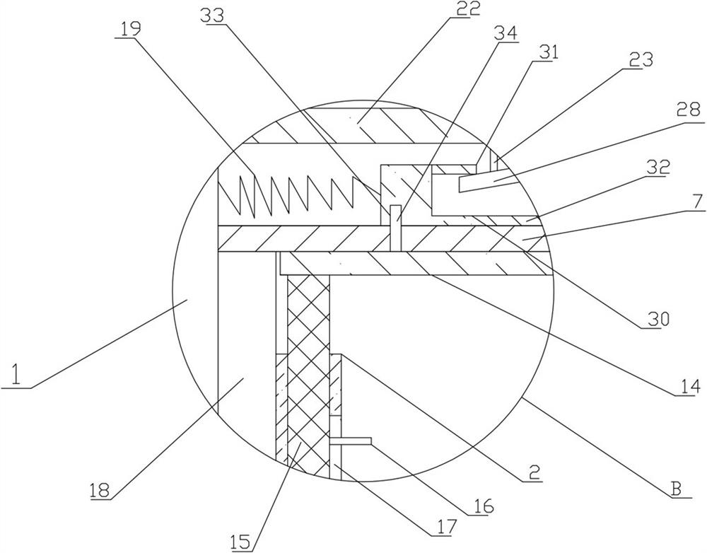
[0032] Such as Figure 1 to Figure 8 As shown, a steel structure for concrete reinforcement includes a concrete structure, and the concrete structure includes a concrete column and a concrete beam 6, and the concrete column includes a left column 1 and a right column 12, and the left column 1 and the right column 12 Concrete beams 6 are connected between the upper parts of the opposite sides of the right column 12, and a reinforced steel structure is also included;

[0033] The reinforced steel structure includes a load-bearing box, a roof assembly, a pulling assembly and a drive assembly. The load-bearing box includes a box body 7 and a fixed plate. The box body 7 is a hollow cuboid with openings on the top surface and left and right sides. The body 7 is sleeved on the outside of the concrete beam 6 from bottom to top. There is a distance between t...


PUM


Abstract

The invention relates to a steel structure for concrete reinforcement. The steel structure comprises a concrete structure and a reinforced steel structure, wherein the reinforced steel structure comprises a bearing box, a top plate assembly, traction assemblies and a driving assembly; the bearing box comprises a box body and a fixing plate; the top plate assembly is arranged between the bottom surface inside the box body and the bottom surface of a concrete beam; the top plate assembly comprises a left top plate assembly and a right top plate assembly with the same structure and size; the traction assemblies comprise a left traction assembly and a right traction assembly with the same structure and size; the left traction assembly and the right traction assembly are respectively arranged at the upper part of the concrete beam above the left top plate assembly and the right top plate assembly and are in a bilateral symmetry state; the driving assembly comprises a sleeve, a bearing plate, a driving rod and a transverse plate; and the sleeve comprises a left sleeve and a right sleeve with the same structure and size. The steel structure solves the problem that the concrete beam can generate bending deformation in the process of bearing great load.

Description

technical field [0001] The invention relates to the technical field of steel structures, in particular to a steel structure for concrete reinforcement. Background technique [0002] Reinforcement refers to taking measures such as strengthening, partially replacing or adjusting the internal force of load-bearing structures, components and related parts that have insufficient reliability or need to be improved in reliability, so that they have the safety, durability and applicability required by the current design specifications and requirements. The reinforcement of concrete structures includes bonded steel reinforcement, carbon fiber reinforcement, pressure grouting reinforcement, planting reinforcement, anchor bolt reinforcement, steel pipe pile reinforcement, etc. [0003] Concrete beam is an important part of the concrete structure of the building. During the long-term use of the concrete beam, in the process of bearing a large load, the concrete beam will appear bending ...

Claims


Application Information

Patent Timeline
Patent Type & Authority Applications(China)
IPC IPC(8): E04G23/02
CPCE04G23/0218
Inventor 刘云
Owner NORTH CHINA UNIV OF WATER RESOURCES & ELECTRIC POWER
Learn More