
Arched grouting device and method

A grouting device and arch technology, which is applied in safety devices, mining devices, earthwork drilling and mining, etc., can solve problems such as shear damage, large shear stress of grouting arches, and inability to fully utilize the strength advantages of underground hidden arches. Achieve the effects of reducing shear stress, reducing ground subsidence deformation, and improving the bonding performance of grout

Active Publication Date: 2021-11-02
SHANDONG UNIV +1
View PDF9 Cites 1 Cited by
  • Summary
  • Abstract
  • Description
  • Claims
  • Application Information

AI Technical Summary

Problems solved by technology

However, at present, the arch grouting technology in engineering still adopts traditional compaction grouting, split grouting and other methods, so that the actual underground grouting arch is stepped, which is quite different from the actual arch shape. Therefore, the grouting arch Under the large shear stress at the step position, shear failure is prone to occur, and the mechanical advantages of the underground arch cannot be fully utilized

Method used


Image

  • Arched grouting device and method
  • Arched grouting device and method
  • Arched grouting device and method

Examples


Embodiment Construction

[0025] The present invention will be further described below in conjunction with the accompanying drawings and embodiments.

[0026] It should be pointed out that the following detailed description is exemplary and intended to provide further explanation to the present application. Unless defined otherwise, all technical and scientific terms used herein have the same meaning as commonly understood by one of ordinary skill in the art to which this application belongs.

[0027] In the present invention, terms such as "upper", "lower", "left", "right", "front", "rear", "vertical", "horizontal", "side", "bottom" etc. indicate The orientation or positional relationship is based on the orientation or positional relationship shown in the accompanying drawings, and is only a relative term determined for the convenience of describing the structural relationship of the various components or elements of the present invention, and does not specifically refer to any component or element in...


PUM


Abstract

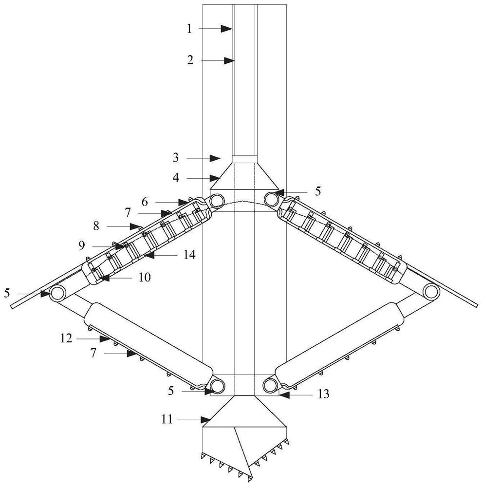
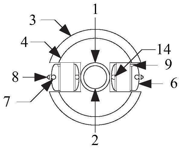
The invention discloses an arched grouting device and method. The arched grouting device comprises a high-pressure jet grouting drill, a pile casing, an umbrella-shaped supporting device, a left-right high-pressure jet grouting system and a front-back grouting system; the high-pressure jet grouting drill comprises a drill rod and a jet-grouting drill bit; the jet-grouting drill bit is installed at the front end of the drill rod; the rear portion of the drill rod is sleeved with an up-down control rod, and a first connecting piece is fixed to the lower portion of the up-down control rod; the umbrella-shaped supporting device comprises at least two sets of supporting devices which are symmetrically arranged relative to the axis of the drill rod; each set of supporting devices comprises a first rigid support and a second rigid support; one end of the first rigid support is hinged to a first connecting piece, and the first connecting piece is matched with the inner wall of the pile casing arranged outside the up-down control rod in a sleeving mode; the other end of the first rigid support is hinged with one end of the corresponding second rigid support; the other end of the second rigid support is hinged to a second connecting piece, and the second connecting piece is fixed to the lower portion of the pile casing; the left-right high-pressure jet grouting system and the front-back grouting system are arranged on the first rigid support; and the front-back grouting system is arranged on the second rigid support.

Description

technical field [0001] The invention relates to a grouting device and a construction process, in particular to an arched grouting device and method in goafs and karst areas, belonging to the field of geotechnical engineering. Background technique [0002] Goaf governance belongs to underground engineering construction, and there are many uncertainties, especially for privately mined minerals. Due to the lack of detailed mining information and post-mining governance, goafs have become a relatively complicated engineering problem. At present, the common goaf treatment method is mainly the grouting filling method. By filling the goaf with cement slurry into the goaf and its cracks, the purpose of sealing the goaf, increasing the stability of the surrounding rock, and reducing the settlement deformation is achieved. . Because goafs are usually widely distributed, the cost of grouting filling the whole section of goafs is greatly increased, especially when there are karst caves ...

Claims


Application Information

Patent Timeline
Patent Type & Authority Applications(China)
IPC IPC(8): E21F15/00E21F15/06E21F17/00
CPCE21F15/005E21F15/00E21F15/06E21F17/00
Inventor 庄培芝岳红亚周国印宋修广于海洋徐程管延华王旌孙子正
Owner SHANDONG UNIV
Learn More