Efficient energy-saving refrigerating system
A refrigeration system, high-efficiency and energy-saving technology, applied in refrigerators, refrigeration components, refrigeration and liquefaction, etc., can solve the problems of small heat exchange contact area of heat exchangers, low refrigeration efficiency of refrigeration systems, etc., to improve the heat exchange contact area, Avoid excessive oil and improve the effect of cooling
- Summary
- Abstract
- Description
- Claims
- Application Information
AI Technical Summary
Problems solved by technology
Method used
Image

Examples
specific Embodiment approach 1
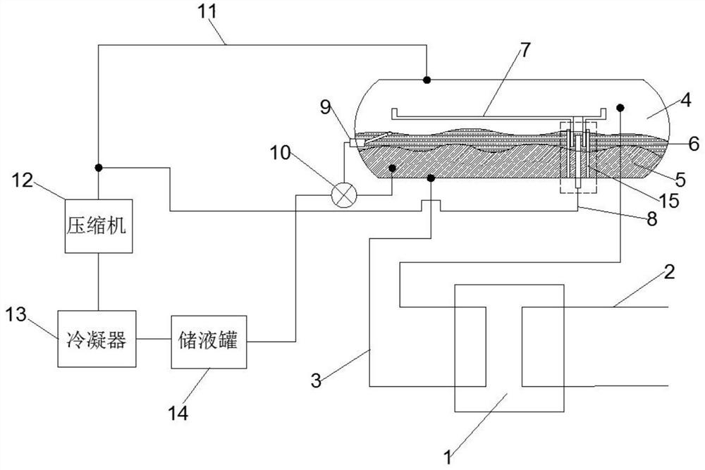
[0027] Specific implementation mode one: combine Figure 1-Figure 2 Describe this embodiment, a high-efficiency energy-saving refrigeration system in this embodiment, including a heat exchanger 1, a separator 4, a compressor 12, and a condenser 13. The heat exchanger 1 and the separator 4 are connected by establishing a connection, and the heat exchanger 1 , the compressor 12 and the condenser 13 are connected in sequence to form a circuit, there is a refrigerant 5 in the separator 4, and the refrigerant 5 in the separator 4 is transported to the heat exchanger 1 for heat exchange, and the refrigerant 5 after heat exchange is Flowing back into the separator 4, the refrigerant 5 after heat exchange is divided into vapor refrigerant and liquid refrigerant. The vapor refrigerant is input into the compressor 12 for compression, and after compression, enters the condenser 13 for condensation. The liquid refrigerant flows into the separator 4 to provide heat exchange for the heat ex...
specific Embodiment approach 2
[0028] Specific implementation mode two: combination Figure 1-Figure 2 Describe this embodiment, a high-efficiency energy-saving refrigeration system in this embodiment, the heat exchanger 1 is a plate heat exchanger, the second connecting pipe 3 is connected between the separator 4 and the heat exchanger 1, and the second The input end of the connecting pipe 3 is connected to the output end of the separator 4, the output end of the second connecting pipe 3 is arranged in the separator 4, the refrigerant 5 flows in the second connecting pipe 3, and the heat exchanger 1 is also provided with The first connecting pipe 2, the first connecting pipe 2 and the second connecting pipe 3 exchange heat in the heat exchanger 1, and the first connecting pipe 2 is used to output cold air. On the basis of the first specific embodiment, when the heat exchanger 1 When a plate heat exchanger is used, the separator 4 is connected to the heat exchanger 1 through pipelines, the first connecting ...
specific Embodiment approach 3
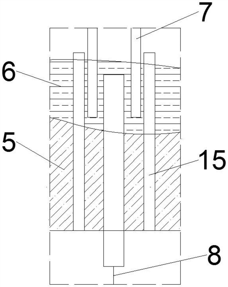
[0029] Specific implementation mode three: combination Figure 1-Figure 2 Describe this embodiment, a high-efficiency energy-saving refrigeration system of this embodiment, the separator 4 also has oil 6, the density of the oil 6 is lower than the density of the refrigerant 5, because the density of the oil 6 is lower than the density of the refrigerant 5 density, so the oil liquid 6 floats above the refrigerant 5, and the function of the oil liquid 6 is to separate the vapor refrigerant and the liquid refrigerant in the separator 4, so as to ensure that the vapor refrigerant and the liquid refrigerant do not fuse, so that The refrigerant 5 input into the heat exchanger 1 is filled with liquid refrigerant, which improves the cooling effect.
PUM
 Abstract
Description
Claims
Application Information
 - R&D
- Intellectual Property
- Life Sciences
- Materials
- Tech Scout
- Unparalleled Data Quality
- Higher Quality Content
- 60% Fewer Hallucinations
Browse by: Latest US Patents, China's latest patents, Technical Efficacy Thesaurus, Application Domain, Technology Topic, Popular Technical Reports.
© 2025 PatSnap. All rights reserved.Legal|Privacy policy|Modern Slavery Act Transparency Statement|Sitemap|About US| Contact US: help@patsnap.com