Ripple noise test system and method

A ripple noise and test system technology, applied in the direction of noise figure or signal-to-noise ratio measurement, etc., can solve the problem that the cut-off frequency of the ripple probe cannot be switched arbitrarily, and achieve the effect of achieving scalability, improving test efficiency and reducing interference.

Pending Publication Date: 2021-11-02
INSPUR SUZHOU INTELLIGENT TECH CO LTD
View PDF9 Cites 0 Cited by
  • Summary
  • Abstract
  • Description
  • Claims
  • Application Information

AI Technical Summary

Problems solved by technology

[0010] In view of the above problems, the purpose of the present invention is to provide a ripple noise testing system and method, which effectively solves the problem that the cut-off frequency of the ripple probe cannot be switched arbitrarily, and improves the convenience of switching the cut-off frequency

Method used


Image

  • Ripple noise test system and method
  • Ripple noise test system and method
  • Ripple noise test system and method

Examples


Embodiment 1

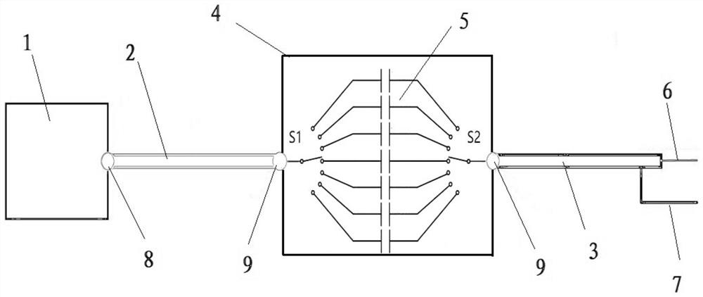
[0045] Such as figure 1 As shown, the present embodiment provides a ripple noise test system, including an oscilloscope 1, a first coaxial cable 2, a second coaxial cable 3 and a PCB board 4, and the PCB board 4 is provided with an isolation capacitance switching circuit 5 , the oscilloscope 1 is connected to the first end of the first coaxial line 2, the second end of the first coaxial line 2 is connected to the output end of the isolation capacitor switching circuit 5, and the first end of the second coaxial line 3 is connected to the isolation capacitor The input end of the switching circuit 5 is connected, and the second end of the second coaxial line 2 is provided with a ripple probe assembly.

[0046] Among them, the ripple probe assembly includes a first metal needle 6 and a second metal needle 7, the first metal needle 6 is welded on the inner core of the second coaxial line 3, and the second metal needle 7 is welded on the second coaxial line 3 on the shielding layer...

Embodiment 2

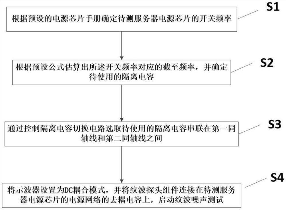
[0050] Based on Example 1, such as figure 2 As shown, the present invention also discloses a ripple noise testing method, which specifically includes the following steps:

[0051] S1: Determine the switching frequency of the server power chip to be tested according to the preset power chip manual.

[0052] S2: Estimate the cut-off frequency corresponding to the switching frequency according to a preset formula, and determine the isolation capacitor to be used.

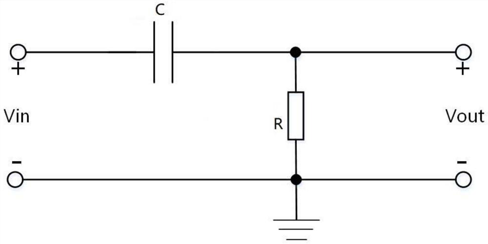
[0053] First, estimate the cut-off frequency f corresponding to the switching frequency f according to the calculation formula of the voltage gain G of the high-pass filter L ;

[0054] The formula for calculating the voltage gain G of the high-pass filter is:

[0055] Among them, G=0.9899, ​​which means that the measurement error is approximately equal to 1%; therefore, the switching frequency f is the cut-off frequency f L 7 times.

[0056] Then, according to the cut-off frequency f L The formula for determi...


PUM


Abstract

The invention provides a ripple noise test system and method. The system comprises an oscilloscope, a first coaxial line, a second coaxial line and a PCB, the PCB is provided with an isolation capacitor switching circuit, the oscilloscope is connected with the first end of the first coaxial line, the second end of the first coaxial line is connected with the output end of the isolation capacitor switching circuit, the first end of the second coaxial line is connected with the input end of the isolation capacitor switching circuit, and the second end of the second coaxial line is provided with a ripple probe assembly. According to the invention, the problem that the cut-off frequency of a ripple probe cannot be switched at will is effectively solved, and the convenience of cut-off frequency switching is improved.

Description

technical field [0001] The present invention relates to the technical field of server testing, and more specifically relates to a ripple noise testing system and method. Background technique [0002] As a high-end computer, a server can provide services such as cloud computing, mass storage, and big data analysis for users in all walks of life. It is an important support for the Internet of Everything in modern society. Due to the server's fast calculation rate, long running time, and high requirements for stability and reliability, the requirements for the server's hardware circuit quality, especially the power supply circuit quality, are extremely stringent. Among them, ripple and noise are two important parameters to measure the quality of power supply circuits. If the ripple and noise exceed the electrical specifications of key chips such as CPU and DDR, it may cause fatal problems such as server crashes and abnormal restarts. With the gradual increase of CPU, DDR and o...

Claims


Application Information

Patent Timeline
Patent Type & Authority Applications(China)
IPC IPC(8): G01R29/26
CPCG01R29/26
Inventor 周景涛
Owner INSPUR SUZHOU INTELLIGENT TECH CO LTD
Why Eureka
Try Eureka