A method and system for dynamic monitoring of data transmission between CPU and FPGA
A dynamic monitoring and data transmission technology, applied in the field of data transmission, can solve problems such as data loss and FPGA blocking, and achieve the effect of ensuring normal and reliable transmission and improving transmission rate
- Summary
- Abstract
- Description
- Claims
- Application Information
AI Technical Summary
Problems solved by technology
Method used
Image

Examples
Embodiment 1
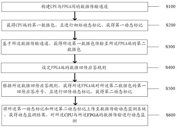
[0029] Such as figure 1 As shown, the embodiment of the present application provides a dynamic monitoring method for data transmission between CPU and FPGA, wherein the method includes:
[0030] Step S100: constructing a data transmission channel between the CPU and the FPGA;
[0031] Step S200: Obtain the first data packet on the CPU side, and perform initial dynamic marking to obtain the first dynamic marking;
[0032]Specifically, when large data is transmitted between the CPU and the FPGA, the back pressure / blocking problem of the FPGA often leads to data loss during the transmission process. In order to solve the problem of data packet loss, in the embodiment of this application, through Dynamic marking of data transmission between CPU and FPGA can effectively avoid the occurrence of such problems. Specifically, a data transmission channel between CPU and FPGA can be constructed, and the data transmission channel is used to transmit data between CPU and FPGA As the comp...
Embodiment 2
[0080] Based on the same inventive concept as a method for dynamic monitoring of data transmission between CPU and FPGA in the foregoing embodiments, the present invention also provides a dynamic monitoring system for data transmission between CPU and FPGA, such as Figure 8 As shown, the system includes:
[0081] The first construction unit 11: the first construction unit 11 is used to construct a data transmission channel between the CPU and the FPGA;
[0082] The first obtaining unit 12: the first obtaining unit 12 is used to obtain the first data packet at the CPU end, and perform initial dynamic marking to obtain the first dynamic marking;
[0083] The second obtaining unit 13: the second obtaining unit 13 is used to obtain the second data packet transmitted from the first data packet to the FPGA end based on the data transmission channel;
[0084] The first setting unit 14: the first setting unit 14 is used to set the data return response rule of the FPGA end;
[0085]...
Embodiment 3
[0121] Refer below Figure 9 An electronic device according to an embodiment of the present application will be described.
[0122] Figure 9 A schematic structural diagram of an electronic device according to an embodiment of the present application is shown.
[0123] Based on the inventive concept of a method for dynamic monitoring of data transmission between CPU and FPGA in the foregoing examples, the present invention also provides a dynamic monitoring system for data transmission between CPU and FPGA, on which a computer program is stored, and the program is executed by a processor When realizing the steps of any method of a CPU and FPGA data transmission dynamic monitoring system mentioned above.
[0124] Among them, in Figure 9 In, bus architecture (represented by bus 300), bus 300 may include any number of interconnected buses and bridges, bus 300 will include one or more processors represented by processor 302 and various types of memory represented by memory 304...
PUM
 Abstract
Description
Claims
Application Information
 - R&D
- Intellectual Property
- Life Sciences
- Materials
- Tech Scout
- Unparalleled Data Quality
- Higher Quality Content
- 60% Fewer Hallucinations
Browse by: Latest US Patents, China's latest patents, Technical Efficacy Thesaurus, Application Domain, Technology Topic, Popular Technical Reports.
© 2025 PatSnap. All rights reserved.Legal|Privacy policy|Modern Slavery Act Transparency Statement|Sitemap|About US| Contact US: help@patsnap.com