

Cable trench and cable trench drainage system
A drainage system and cable trench technology, which is applied in waterway systems, sewer systems, drainage structures, etc., can solve problems such as the impact of cable life and the inability to quickly discharge accumulated water, so as to avoid excessive temperature, effectively dissipate heat, and increase service life Effect
- Summary
- Abstract
- Description
- Claims
- Application Information
AI Technical Summary
Problems solved by technology
Method used
Image

Examples
Embodiment 1
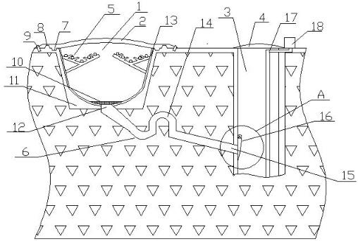
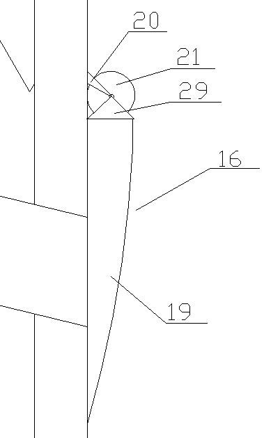
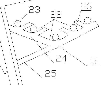
[0034] Such as Figure 1-5 As shown, this embodiment provides a cable trench and a cable trench drainage system, including a cable trench body 1, a drainage channel 6 and a water collection well 3, and the cable trench body 1 includes a cable trench 11, several cable supports 5 and a cable trench Cover plate 2, the cable bracket 5 is arranged on the side wall of the cable trench 11, the cable trench cover plate 2 is arranged on the upper part of the cable trench 11, the drainage channel 6 includes a water inlet section 12, an elbow section 14 and a water outlet section 15, one end of the water inlet section 12 communicates with the bottom of the cable trench 11, the other end of the water inlet section 12 communicates with one end of the elbow section 14, and the other end of the elbow section 14 communicates with the One end of the water outlet section 15 is connected, the other end of the water outlet section 15 is connected with the side wall of the water collection well 3,...
Embodiment 2
[0042] This embodiment is an improvement made on the basis of Embodiment 1. In Embodiment 1, the accumulated water is discharged into the water collection well 3 and enters the soil mainly through recharging. Generally, no human intervention is required, but when it is in the rainy season or it is relatively low-lying At the same time, when the water level in the water collection well 3 is too high, there is a certain degree of potential safety hazard. A cover plate 4 is set at the well head of the water collection well 3 to prevent accidental fall. The accumulated water in the water collection well 3 is pumped out to avoid excessive accumulated water. If necessary, a water level gauge can be added for observation.
PUM
 Abstract
Description
Claims
Application Information