Integrated variable speed driver of electric automobile

A variable speed drive, electric vehicle technology, applied in the field of key automotive parts, to achieve the effect of increasing the crushing strength

Pending Publication Date: 2021-11-02
蒋应林
View PDF0 Cites 0 Cited by
  • Summary
  • Abstract
  • Description
  • Claims
  • Application Information

AI Technical Summary

Problems solved by technology

[0004] In order to solve the above technical problems, the present invention provides an electric vehicle integrated variable speed drive to solve the existing problems

Method used


Image

  • Integrated variable speed driver of electric automobile
  • Integrated variable speed driver of electric automobile
  • Integrated variable speed driver of electric automobile

Examples


Embodiment 1

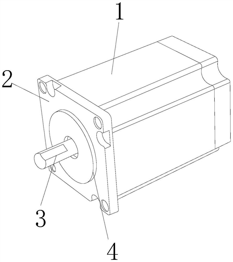
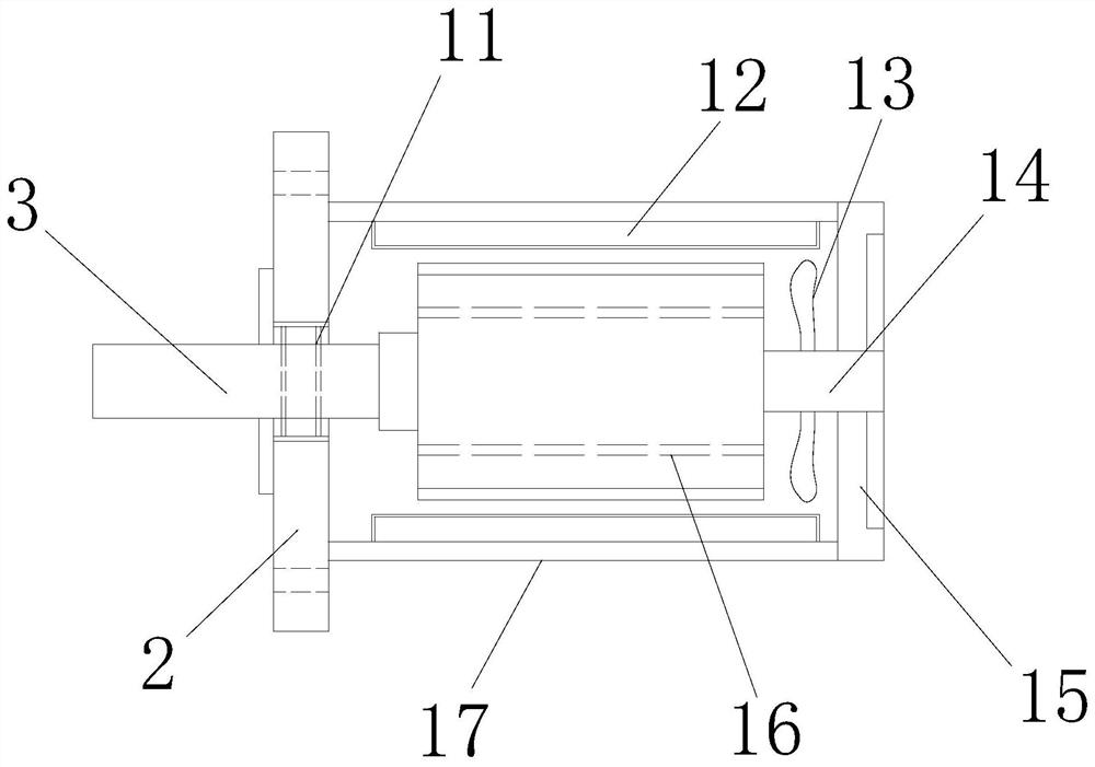
[0030] as attached figure 1 to attach Figure 6 Shown:

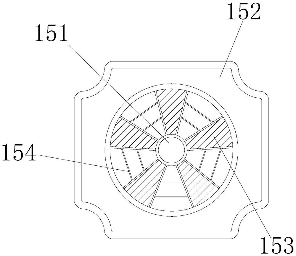
[0031] The invention provides an integrated variable speed drive for electric vehicles, the structure of which includes a body 1, a connecting cover 2, a rotating shaft 3, and a shaft sleeve 4, the left end of the body 1 is embedded and connected to the right end of the connecting cover 2, and the right end of the rotating shaft 3 is connected to the body 1. The left end is welded and connected. The right end of the shaft sleeve 4 is embedded and installed on the left end of the connecting cover 2. The body 1 includes a bearing 11, an electromagnetic coil 12, a fan blade 13, a connecting shaft 14, a heat dissipation cover 15, a rotor 16, and a sealing wall 17. , the inner side of the bearing 11 is connected with the outer side of the rotating shaft 3 with interference fit, the outer side of the electromagnetic coil 12 is welded and connected with the inner side of the sealing wall 17, the inner side of the fan blade 13...

Embodiment 2

[0039] as attached Figure 7 to attach Figure 9 Shown:

[0040] The present invention provides an integrated variable speed drive for an electric vehicle. The force plate 432 includes a connecting plate 321, a fixed sleeve 322, a sliding tube 323, a press-cut block 324, an elastic block 325, and a fixed wall 326. The inner side of the connecting plate 321 It is welded to the outer side of the fixed wall 326, the outer side of the fixed sleeve 322 is engaged with the inner side of the sliding tube 323, the outer side of the sliding tube 323 is movably engaged with the inner side of the sliding ring 433, and the outer side of the pressing block 324 is vertically installed on the fixed wall 326 inside, the outside of the elastic block 325 is embedded and connected with the inside of the fixed wall 326, the left end of the connecting plate 321 is embedded and connected with the right end of the installation block 431, and the press-cut block 324 is staggered and installed on the...


PUM


Abstract

The invention provides an integrated variable-speed driver of an electric automobile. The driver structurally comprises a machine body, a connecting cover, a rotating shaft and a shaft sleeve, the left end of the machine body is fixedly connected with the right end of the connecting cover in an embedded mode, the right end of the rotating shaft is connected with the left end of the machine body in a welded mode, and the right end of the shaft sleeve is fixedly installed at the left end of the connecting cover in an embedded mode. The machine body comprises a bearing, an electromagnetic coil, fan blades, a connecting shaft, a heat dissipation cover, a rotor and a sealing wall, the inner side of the bearing is connected with the outer side of a rotating shaft in an interference fit mode, the outer side of the electromagnetic coil is connected with the inner side of the sealing wall in a welded mode, and the inner sides of the fan blades are fixedly connected with the outer side of the connecting shaft in an embedded mode. When the engine oil is caked on the cleaning rod in the ventilation plate, through vibration generated by rotation of the rotor in the electromagnetic coil, the vibration borne by the connecting block is conveyed into the vibration force plate from the conduction plate, the stress plate is impacted and extruded inwards through vibration, and cakes are crushed through the impact block in the pressing block so that the cakes are prevented from being blocked in the ventilation opening.

Description

technical field [0001] The invention belongs to the technical field of key components of automobiles, and more specifically relates to an integrated variable speed drive for electric vehicles. Background technique [0002] The variable-speed drive motor is one of the main core components of electric vehicles. The central control system conducts conductive pressure on the stator, so that the internal electromagnetic coil is energized and has a physical reaction with the permanent magnet in the rotor, so that the permanent magnet drives the rotating shaft in the electromagnetic coil. Rotate, and can regulate the rotation speed of the rotating shaft by controlling the magnitude of the voltage, so as to realize the speed change function of the drive motor to the car. [0003] Because the driving motor needs to be maintained with oil when it is in use, and the oil will burn at high temperature to form sludge, and the sludge contains iron filings from gear wear and carbon deposits...

Claims


Application Information

Patent Timeline
IPC IPC(8): H02K15/00H02K15/14H02K5/22B02C19/00
CPCH02K15/00H02K15/14H02K5/22B02C19/0012B02C2201/06Y02T10/64
Inventor 蒋应林
Owner 蒋应林
Why Eureka
Try Eureka