Supercharge Your Innovation With Domain-Expert AI Agents!

A debuggable hydraulic rotor lamination tool

A technology for laminating tooling and rotors, which is applied in the manufacture of stator/rotor bodies, electromechanical devices, and cleaning methods using tools, etc. It can solve the problems of long production cycle, low production efficiency, and positioning size differences, and reduce the number of impurities, Improve cleanliness and ensure quality

Active Publication Date: 2022-07-01
无锡市亨达电机有限公司
View PDF6 Cites 0 Cited by
  • Summary
  • Abstract
  • Description
  • Claims
  • Application Information

AI Technical Summary

Problems solved by technology

[0005] In order to make up for the deficiencies of the existing technology and solve the problem that there are too many models of synchronous motor rotors, the large models basically adopt the lamination process with shafts, but due to the differences in models and positioning dimensions, it is necessary to make a lot of lamination tooling, and The quality is still uncontrollable, the production efficiency is low, and the production cycle is long. The invention proposes a kind of adjustable hydraulic rotor lamination tooling.

Method used


Image

  • A debuggable hydraulic rotor lamination tool
  • A debuggable hydraulic rotor lamination tool
  • A debuggable hydraulic rotor lamination tool

Examples


Embodiment 2

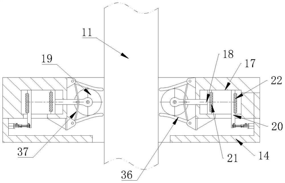
[0052] see Figure 2-5 As shown in the comparison example 1, as another embodiment of the present invention, a cleaning box 14 is fixed on the hydraulic cylinder 11; the hydraulic cylinder 11 is slidably connected with the cleaning box 14; the inner side of the cleaning box 14 The wall is provided with a plurality of groups of piston chambers 17; the position of the piston chamber 17 corresponds to the hydraulic cylinder 11; a piston rod 18 is slidably connected inside the piston chamber 17; Cleaning roller 19; a control plate 20 is slidably connected inside the piston cavity 17; an electric cylinder is installed on the inner wall of the cleaning box 14; the control plate 20 is fixedly connected with the output end of the electric cylinder; the piston rod 18 side A first magnet 21 is fixed on the wall; a second magnet 22 is fixed on the side wall of the control board 20; during use, when the hydraulic cylinder 11 outputs mechanical energy on the cleaning box 14, it is in the c...

Embodiment 3

[0062] see Image 6 As shown, compared with the above-mentioned embodiment, as another embodiment of the present invention, a plurality of groups of flexible friction cleaning sheets 38 are fixedly connected to the side walls of the cleaning bristles 36; Three elastic pull cords 39; by adding multiple sets of flexible friction cleaning sheets 38 to the side walls of the cleaning bristles 36, when the cleaning bristles 36 are in contact with the cleaning roller 19, the flexible friction cleaning sheets 38 are tightly pressed against the cleaning roller 19 On the side wall of the cleaning roller 19, the flexible friction cleaning sheet 38 extends into the side wall of the cleaning roller 19, where the cleaning bristles 36 are not easy to contact, so that after the side wall of the cleaning roller 19 is in contact with the cleaning bristles 36, it will be cleaned more cleanly.

[0063] The overall working principle is:

[0064] 1. Place the assembled stacking tool on the press t...


PUM


Abstract

The invention belongs to the technical field of lamination of synchronous permanent magnet motor rotors, in particular to a debuggable hydraulic rotor lamination tool, comprising a table top fixing plate; a hydraulic cylinder is arranged on the top of the table top fixing plate; M6*30 inner hexagonal cylindrical screws are fixed on the table top fixing plate; the output end of the hydraulic cylinder is fixed with a hydraulic cylinder fixing plate; the top of the hydraulic cylinder fixing plate is provided with M6*20 inner hexagonal cylindrical screws; The hexagonal cylindrical screw M6*20 is fixed on the hydraulic cylinder fixing plate through the lamination base fixing plate; the lamination base is placed on the top of the lamination base fixing plate; the rotor iron core lower pressure plate is installed on the top of the lamination base At the same time, the hydraulic cylinder adopts servo control to achieve highly accurate positioning. At the same time, a visual pressure sensor is added to the oil circuit, which can sense the pressure of the stack in real time and ensure the quality of the stack.

Description

technical field [0001] The invention belongs to the technical field of lamination of synchronous permanent magnet motor rotors, in particular to a debuggable hydraulic rotor lamination tool. Background technique [0002] The rotor of the motor is an important part inside the motor. When the rotor is working, it is in a state of high-speed rotation. At the same time, the rotor is also a necessary part in the motor, generator and gas turbine. [0003] In the prior art, there are also some technical solutions for the lamination of synchronous permanent magnet motor rotors. For example, a Chinese patent with the application number of 2019111837188 discloses the permanent magnet motor rotor processing technology and rotor assembly. The riveting punching machine punches into rotor pieces with rotor slots, riveting areas and welding openings; the self-stacking riveting punching machine rives multiple rotor pieces to each other through the riveting area to form the rotor core; laser...

Claims


Application Information

Patent Timeline
Patent Type & Authority Patents(China)
IPC IPC(8): H02K15/02H02K15/03B08B1/04B08B5/02
CPCH02K15/02H02K15/03B08B5/02B08B1/32
Inventor 洪泽伟
Owner 无锡市亨达电机有限公司
Features
  • R&D
  • Intellectual Property
  • Life Sciences
  • Materials
  • Tech Scout
  • Unparalleled Data Quality
  • Higher Quality Content
  • 60% Fewer Hallucinations
Learn More