
Cleaning mechanism and cleaning equipment

A technology for cleaning mechanism and cleaning equipment, applied in the field of cleaning, can solve the problems of easy damage and low controllability of tools

Pending Publication Date: 2021-11-05
CHONGQING FOUNDER HI TECH ELECTRONICS +1
View PDF14 Cites 0 Cited by
  • Summary
  • Abstract
  • Description
  • Claims
  • Application Information

AI Technical Summary

Problems solved by technology

[0005] This application provides a cleaning mechanism and cleaning equipment, aiming to solve the problem of low controllability and easy damage of knives in the cleaning process

Method used


Image

  • Cleaning mechanism and cleaning equipment
  • Cleaning mechanism and cleaning equipment
  • Cleaning mechanism and cleaning equipment

Examples


Embodiment 1

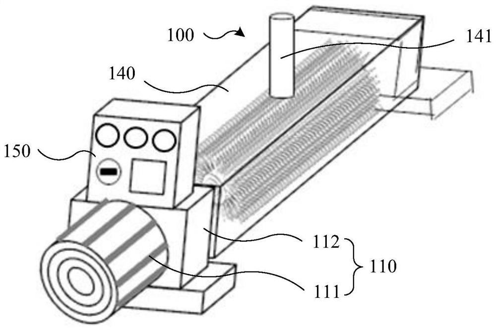
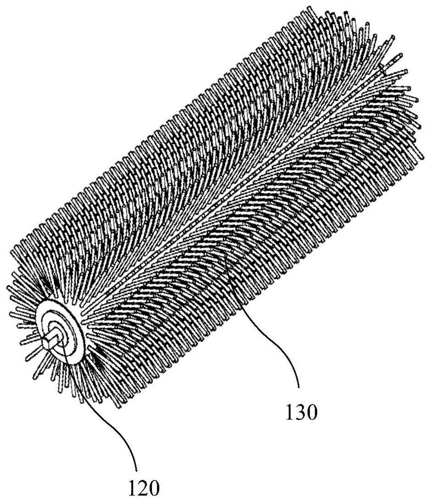
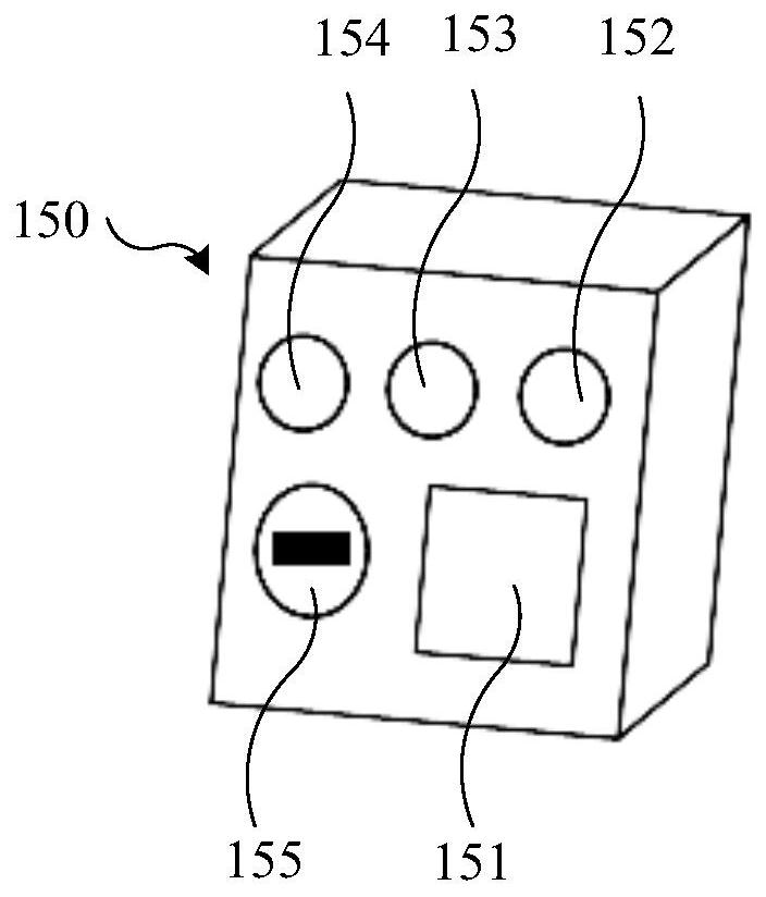
[0054] figure 1 It is a schematic structural diagram of the cleaning mechanism provided in Embodiment 1 of the present application. figure 2 An assembly drawing of the rotating part and cleaning part of the cleaning mechanism provided in Embodiment 1 of the present application. image 3 It is a schematic structural diagram of the operation panel of the cleaning mechanism provided in Embodiment 1 of the present application.

[0055] refer to Figure 1 to Figure 3 As shown, the cleaning mechanism 100 provided in a possible embodiment of the present application includes a driving member 110, a rotating member 120 and a cleaning member 130, the rotating member 120 is connected with the driving member 110, and the cleaning member 130 is arranged on the rotating member 120; The outer cover of the component 120 is provided with a transparent cover 140 , and an accommodating cavity is formed between the transparent cover 140 and the rotating component 120 .

[0056] The cleaning m...

Embodiment 2

[0074] Figure 4 It is a schematic structural diagram of the cleaning equipment provided in Example 2 of the present application. Figure 5 It is a schematic structural diagram of the conveying assembly (including the stopper) of the cleaning device provided in Embodiment 2 of the present application. Image 6 It is a schematic structural diagram of the conveying assembly (without the stopper) of the cleaning device provided in Embodiment 2 of the present application. Figure 7 It is a schematic structural diagram of the cutterhead (including cutters) of the cleaning device provided in Example 2 of the present application. Figure 8 It is a schematic structural diagram of the limiting member of the cleaning equipment provided in the second embodiment of the present application.

[0075] refer to Figure 4 to Figure 8As shown, on the basis of the first embodiment, a possible embodiment of the present application provides a cleaning device configured with the cleaning mechani...


PUM


Abstract

The invention relates to the technical field of cleaning, in particular to a cleaning mechanism and cleaning equipment, and aims at solving the problems that in the cleaning process, a cutter is low in controllability and prone to damage. The cleaning mechanism comprises a driving part, a rotating part connected with the driving part, and a cleaning part arranged on the rotating part. A transparent cover covers the rotating part, so that the use condition of the cleaning mechanism and the cleaning state of the cutter can be observed in time when the cutter is cleaned, the cutter can be effectively controlled in time in the cleaning process, the controllability of the cutter in the cleaning process is improved, and the damage probability of the cutter is reduced; and cutting chips can be prevented from splashing in the cleaning process to accidentally injure operators. A containing cavity used for containing the cleaning part is formed between the transparent cover and the rotating part, and the interval is formed between the cleaning part and the inner wall face of the transparent cover, so that collection of the cutting chips generated by cleaning is facilitated, and reduction or elimination of frictional wear between the cleaning part and the transparent cover is facilitated.

Description

technical field [0001] The present application relates to the field of cleaning technology, in particular to a cleaning mechanism and cleaning equipment. Background technique [0002] After the tool completes the machining task of the workpiece to be processed, the surface of the tool needs to be cleaned for the next use. [0003] Printed Circuit Board (PCB) is the carrier for the electrical connection of electronic components. Drilling holes in PCB is an important process of PCB board manufacturing. Special drills are usually used for PCB drilling, and the diameter of the drills is 0.2 mm to several mm. between. After the drill is drilled on the PCB, it is easy to leave cutting chips on the drill, and the drill is cleaned by cleaning equipment. Wherein, the cleaning device includes a closed casing, a motor and a brush cylinder connected to the output end of the motor. The motor and the brush cylinder are arranged in the closed casing, and bristles are arranged on the brus...

Claims


Application Information

Patent Timeline
Patent Type & Authority Applications(China)
IPC IPC(8): B08B1/04B08B1/00B08B13/00
CPCB08B13/00B08B1/12B08B1/32
Inventor 徐竟成李金鸿雷川曹磊磊
Owner CHONGQING FOUNDER HI TECH ELECTRONICS
Learn More