Filter shell drilling equipment capable of detecting

A filter housing, drilling equipment technology, applied in drilling/drilling equipment, measuring/indicating equipment, boring/drilling and other directions, can solve the problems of deformation, excessive force, small wall thickness, etc.

Inactive Publication Date: 2021-11-05
长沙市兴琦自动化设备有限公司
View PDF0 Cites 0 Cited by
  • Summary
  • Abstract
  • Description
  • Claims
  • Application Information

AI Technical Summary

Problems solved by technology

[0002] like figure 2 As shown, it is a schematic diagram of the processing of a shell product 11. The product 11 includes a main body 12, four arc blocks are arranged under the side of the main body, and four side grooves 13 are opened on the side of the main body 12, and a Roof holes, therefore, drilling operations are required, and the length and position of the side grooves also need to be detected. However, the existing drilling and side groove inspections are carried out separately, and at least two sets of mechanical equipment are required to be carried out separately. In the process of drilling, how to realize the clamping position of the main body 12 is also a technical problem. The main body 12 is a shell with a small wall thickness. If it is clamped directly by force from the side, it is easy to be deformed due to excessive force

Method used


Image

  • Filter shell drilling equipment capable of detecting
  • Filter shell drilling equipment capable of detecting
  • Filter shell drilling equipment capable of detecting

Examples


Embodiment Construction

[0023] In order to enable those skilled in the art to better understand the technical solution of the present invention, the present invention will be described in detail below in conjunction with the accompanying drawings. The description in this part is only exemplary and explanatory, and should not have any limiting effect on the protection scope of the present invention. .

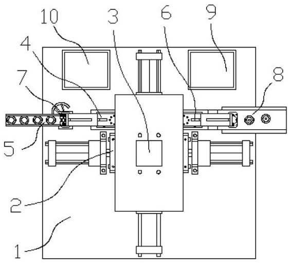
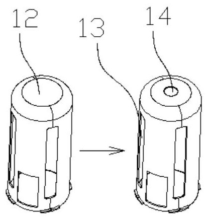
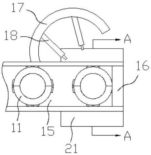
[0024] Such as Figure 1-2 with Figure 5-7 As shown, the specific structure of the present invention is: a detectable filter casing drilling equipment, including a frame 1, the frame 1 is provided with a locking mechanism 2 and a drilling hole located above the locking mechanism 2 Device 3, the clamping mechanism 2 includes a square clamping discharge block 31 arranged on the frame 1, the center of the clamping discharge block 31 is provided with a discharge hole matched with the product 11, and the clamping The center of the four sides of the discharge block 31 is clamped with the mouth 33, and the...


PUM


Abstract

The invention relates to filter shell drilling equipment capable of detecting. The filter shell drilling equipment comprises a rack, a clamping mechanism and a drilling device, wherein the clamping mechanism comprises a clamping discharging block arranged on the rack, a discharging hole matched with a product is formed in the center of the clamping discharging block, the centers of the four side faces of the clamping discharging block are tightly clamped with matching openings, a clamping matching groove enabling the clamping matching opening to be communicated with the discharging hole is formed between the center of the clamping matching opening and the discharging hole, the clamping matching opening is matched with a clamping device; the clamping device comprises a clamping air cylinder, the clamping air cylinder is connected with a clamping socket, the clamping socket is connected with a clamping insertion block which can penetrate through the clamping matching opening, and the width of the clamping insertion block is matched with that of the side groove; pressure sensors are embedded in the upper side face and the lower side face of the clamping insertion block, a matching opening consistent with the discharging hole in size is formed in the portion, under the discharging hole, of the plate face of the rack, a clamping top base is inserted into the matching opening in a penetrating mode, and the clamping top base is connected with a clamping lifting device arranged below the plate face of the rack and can be matched with the side groove to clamp the main body, and detect the side groove.

Description

technical field [0001] The invention relates to the field of automatic processing equipment, in particular to a detectable filter shell drilling equipment. Background technique [0002] Such as figure 2 As shown, it is a schematic diagram of the processing of a shell product 11. The product 11 includes a main body 12, four arc blocks are arranged under the side of the main body, and four side grooves 13 are opened on the side of the main body 12, and a Roof holes, therefore, drilling operations are required, and the length and position of the side grooves also need to be detected. However, the existing drilling and side groove inspections are carried out separately, and at least two sets of mechanical equipment are required to be carried out separately. During the drilling process, how to realize the clamping position of the main body 12 is also a technical problem. The main body 12 is a shell with a small wall thickness. If it is clamped directly by force from the side, it...

Claims


Application Information

Patent Timeline
IPC IPC(8): B23B41/00B23Q3/08B23B47/22B23Q7/00B23Q11/08B23Q17/00
CPCB23Q3/08B23Q17/00B23B41/00B23Q5/22B23Q11/08B23Q7/00
Inventor 高兴冯晓军郭梓钿
Owner 长沙市兴琦自动化设备有限公司
Why Eureka
Try Eureka