High-precision plunger forming process

A molding process and high-precision technology, applied in the field of plunger pumps, can solve the problems of low efficiency of plunger processing and labor consumption, and achieve the effects of increasing production output, saving processing time, and saving power output.

Inactive Publication Date: 2021-11-05
JIANGSU HENGYUAN HYDRAULIC
View PDF1 Cites 2 Cited by
  • Summary
  • Abstract
  • Description
  • Claims
  • Application Information

AI Technical Summary

Problems solved by technology

[0005] The purpose of the present invention is to provide a plunger high-precision molding process for the deficiencies of the prior art. By sequentially completing the upper loading work, slotting work, ball milling work and blanking work of the plunger on one device, the entire process can be realized. The continuous tightness of the work, the whole work can realize unmanned operation, and the degree of automation is high, which solves the problem that the plunger in the prior art is manually uploaded to the processing lathe when the plunger is processed, and the processing is completed Finally, it is manually removed and stored, so while consuming manual labor, the efficiency of plunger processing is very low.

Method used


Image

  • High-precision plunger forming process
  • High-precision plunger forming process
  • High-precision plunger forming process

Examples


Embodiment 1

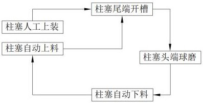
[0068] Such as figure 1 As shown, a plunger high-precision forming process includes the following steps:

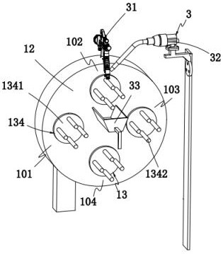
[0069] Step 1: Plungers are manually installed. Firstly, several plungers are manually installed on the rotating assembly 13 in sequence for the first time, and the rotating assembly 13 is switched to the slotting station 102 driven by the turntable 12;

[0070] Step 2: The tail end of the plunger is slotted, the engaging part 133 moves to the second drive assembly 22, the clamping assembly 34 cooperates with the positioning shaft 1342 to complete the clamping of the plunger, and the slotting mechanism 3 performs slotting work on the plunger, After all the plungers complete the slotting work, the first driving assembly 21 drives the turntable 12 to continue to rotate and drive it to switch to the ball milling station 103;

[0071] Step 3: Ball milling at the head end of the plunger, the ball milling mechanism 5 completes the ball milling work on each plunger in turn; aft...

Embodiment 2

[0077] The components in this embodiment that are the same as or corresponding to those in the above embodiment use the corresponding reference numerals. For the sake of simplicity, only the differences from the above embodiment will be described below. The difference between this embodiment and the above-mentioned embodiment is:

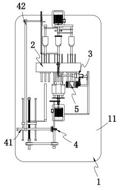
[0078] Such as figure 2 As shown, an automatic production device for plunger pump body accessories includes: a carrying mechanism 1, and the carrying mechanism 1 is sequentially provided with a feeding station 101, a slotting station 102, a ball milling station 103 and a lower material station 104;

[0079] A driving mechanism 2, the driving mechanism 2 drives several groups of component units on the carrying mechanism 1 to sequentially transmit to each station;

[0080] A slotting mechanism 3, the slotting mechanism 3 is arranged on the slotting station 102 and it is used to perform circular slotting work on the component units on the slotting s...

Embodiment 3

[0125] The components in this embodiment that are the same as or corresponding to those in the above embodiment use the corresponding reference numerals. For the sake of simplicity, only the differences from the above embodiment will be described below. The difference between this embodiment and the above-mentioned embodiment is:

[0126] further, such as Figure 9 As shown, the feeding assembly 41 includes:

[0127] The input assembly 411, the input assembly 411 includes an input channel 4111 coaxially arranged with the positioning shaft 1342 at the lower end, a push rod 4112 slidingly arranged in the input channel 4111, and a push rod 4112 for driving the push rod 4112 to advance The screw nut unit 4113 and the first synchronous wheel 4114 for driving the screw nut unit 4113 to start, the workpieces are sequentially matched and lying in the input channel 4111; and

[0128] The first linkage assembly 412, the first linkage assembly 412 includes a first driving gear wheel 41...


PUM


Abstract

The invention provides a high-precision plunger forming process. The high-precision plunger forming process comprises the following steps that 1, plungers are manually loaded; 2, the tail ends of the plungers are slotted, a clamping part moves to a second driving assembly, a clamping assembly is matched with a positioning shaft to clamp the plungers, a slotting mechanism carries out slotting work on the plungers, and after slotting work of all the plungers is completed, a first driving assembly drives a rotary disc to continue to rotate to drive the plungers to be switched to a ball milling station; 3, the head ends of the plungers are ball-milled; 4, the plungers are automatically discharged; and 5, the plungers are automatically fed. The problems that when the plungers are machined again, the plungers are manually loaded to a machining lathe, and after machining is completed, the plungers are manually taken down and stored, so that the manual labor force is consumed, and meanwhile the plunger machining efficiency is very low are solved.

Description

technical field [0001] The invention relates to the technical field of plunger pumps, in particular to a high-precision forming process for plungers. Background technique [0002] During the working process of the swash plate axial piston pump and motor, the plunger has two motion modes: axial movement and rotation around the central axis. For swash plate axial piston pumps and piston motors, the plunger body is a cylindrical structure, and the movement in the cylinder includes two types of movement, horizontal movement and self-rotation. The plunger is affected by the pressure of the hydraulic oil. When the plunger moves horizontally in the cylinder, it will form a certain angle with the horizontal direction, which will cause mechanical contact between the two ends of the plunger and the outer wall of the cylinder, resulting in wear; When the plug rotates around the drive shaft, the plunger itself will rotate, and the rotation of the plunger will aggravate the wear of the ...

Claims


Application Information

Patent Timeline
Patent Type & Authority Applications(China)
IPC IPC(8): B23P15/00B23P23/00B23Q7/00B23Q7/02B23K26/36B23K26/70
CPCB23P15/00B23P23/00B23Q7/00B23Q7/02B23K26/36B23K26/703
Inventor 顾海烨
Owner JIANGSU HENGYUAN HYDRAULIC
Why Eureka
Try Eureka