
Automatic centering mechanism for T-shaped guide rail machining and control method for automatic centering mechanism

A technology of automatic centering and guide rail processing, which is applied in the direction of metal processing machinery parts, metal processing equipment, manufacturing tools, etc. Error, the effect of improving stability

Active Publication Date: 2021-11-05
MARAZZI JIANGSU ELEVATOR GUIDE RAIL
View PDF9 Cites 0 Cited by
  • Summary
  • Abstract
  • Description
  • Claims
  • Application Information

AI Technical Summary

Problems solved by technology

[0003]In the existing technology, since the cutter of the planer is usually circular, it is difficult to center the guide rail, and workers need to predict the cutting amount based on experience , so that the machining accuracy of the guide rail is difficult to guarantee

Method used


Image

  • Automatic centering mechanism for T-shaped guide rail machining and control method for automatic centering mechanism
  • Automatic centering mechanism for T-shaped guide rail machining and control method for automatic centering mechanism
  • Automatic centering mechanism for T-shaped guide rail machining and control method for automatic centering mechanism

Examples


Embodiment Construction

[0040] The following will clearly and completely describe the technical solutions in the embodiments of the present invention with reference to the accompanying drawings in the embodiments of the present invention. Obviously, the described embodiments are only some, not all, embodiments of the present invention.

[0041] It should be noted that when an element is referred to as being “fixed” to another element, it can be directly on the other element or there can also be an intervening element. When an element is referred to as being "connected to" another element, it can be directly connected to the other element or intervening elements may also be present. The terms "vertical," "horizontal," "left," "right," and similar expressions are used herein for purposes of illustration only and are not intended to represent the only embodiments.

[0042] Unless otherwise defined, all technical and scientific terms used herein have the same meaning as commonly understood by one of ordi...


PUM


Abstract

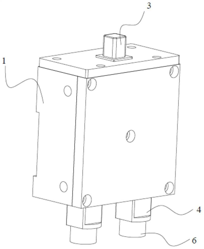
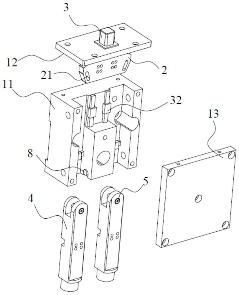
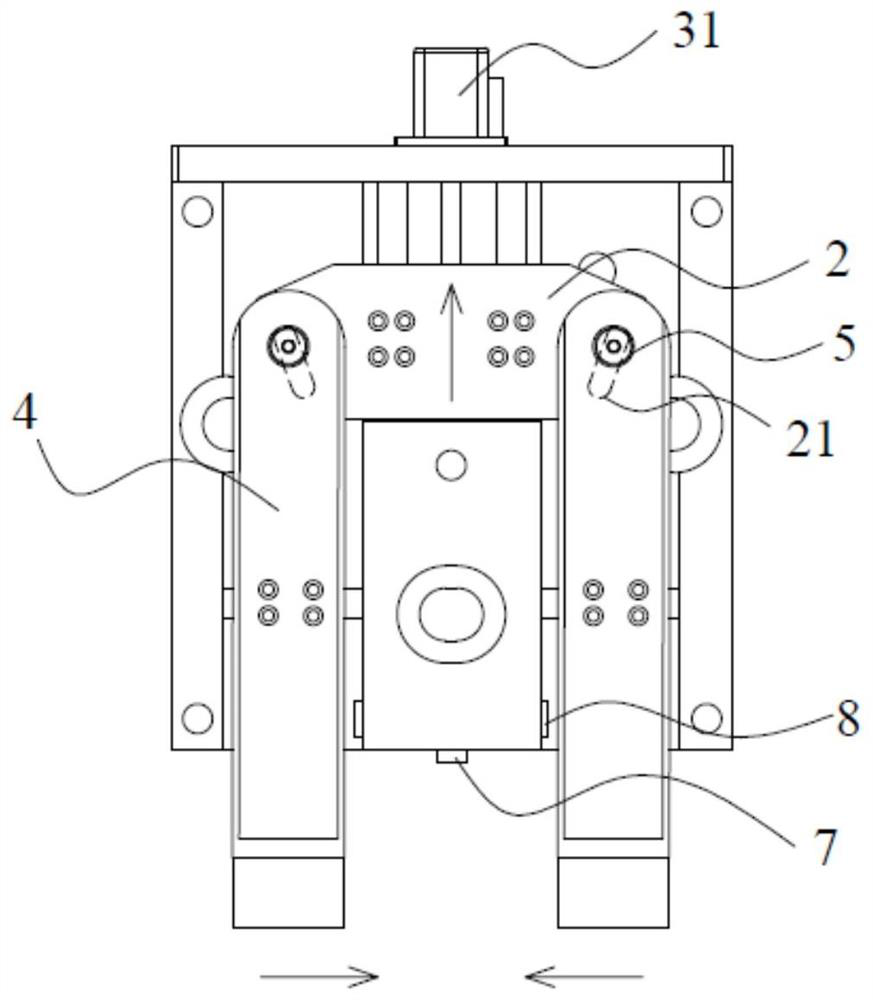
The invention relates to the technical field of elevator part manufacturing, in particular to an automatic centering mechanism for T-shaped guide rail machining and a control method for the automatic centering mechanism. The automatic centering mechanism comprises a fixing assembly, a connecting plate, a driving assembly and two centering cutter bars, and two connecting holes of the connecting plate are gradually folded inwards from top to bottom in the vertical direction; and the ends, close to the connecting plate, of the centering cutter bars are provided with guide columns, the guide columns are arranged in the connecting holes, the driving assembly drives the connecting plate to move in the vertical direction, the guide columns move in the connecting holes in the inclination direction of the connecting holes, and the two centering cutter bars synchronously move in the horizontal direction in the mode that the two centering cutter bars get close to each other or get away from each other. Through the arrangement of the centering mechanism, the T-shaped guide rail is limited between the two centering cutter bars during machining, so that it is guaranteed that the symmetric center lines of the guide rail and a planer tool are centered, the planer can conveniently cut the guide face of the guide rail, the symmetric tolerance of the guide face and the neck of the guide rail is reduced, and the machining precision of the guide rail is improved.

Description

technical field [0001] The invention relates to the technical field of elevator component manufacturing, in particular to an automatic centering mechanism for T-shaped guide rail processing and a control method thereof. Background technique [0002] The elevator guide rail is an elevator component composed of steel rails and connecting plates, which play a guiding role and bear the impact force when the elevator brakes. Elevator guide rails include a T-shaped cross-sectional shape, and the guide surface needs to be cut by a gantry planer during processing to improve the machining accuracy of the guide surface and provide a benchmark for subsequent guide roller tenon groove processing, and the guide of the T-shaped guide rail The symmetry tolerance between the surface and the neck of the guide rail should be less than 0.16 times the width of the neck. Therefore, when using the planer to process the guide rail, it is necessary to ensure the alignment of the center line of the ...

Claims


Application Information

Patent Timeline
Patent Type & Authority Applications(China)
IPC IPC(8): B23Q3/18
CPCB23Q3/18B23Q2703/10
Inventor 庄卫东黄涤张凯刘香松
Owner MARAZZI JIANGSU ELEVATOR GUIDE RAIL
Learn More