Metal cutting machine tool convenient for collecting chippings, and using method thereof

A metal cutting and chipping technology, which is applied to metal processing machinery parts, metal processing equipment, clamping, etc., can solve the problems of increasing cutting machine wear, poor clamping effect, and affecting machining accuracy, so as to reduce wear and clamp The effect is good and the effect of increasing the service life

Inactive Publication Date: 2021-11-05
陈先取
View PDF0 Cites 2 Cited by
  • Summary
  • Abstract
  • Description
  • Claims
  • Application Information

AI Technical Summary

Problems solved by technology

[0003] Existing cutting machines will splash a lot of debris when cutting metal. These debris not only harm the human body, but also easily enter the cutting machine. The wear of the cutting machine affects the service life of the cutting machine. In addition, the clamping mechanism of the existing cutting machine cannot clamp circular and square materials at the same time. A few cutting machines that can clamp circular and square materials cannot be adjusted. Only one type of material can be clamped, and the clamping effect is poor. Therefore, it is urgent to design a metal cutting machine tool that is easy to collect debris and its use method to solve the above problems

Method used


Image

  • Metal cutting machine tool convenient for collecting chippings, and using method thereof
  • Metal cutting machine tool convenient for collecting chippings, and using method thereof
  • Metal cutting machine tool convenient for collecting chippings, and using method thereof

Examples


Embodiment Construction

[0036] The following will clearly and completely describe the technical solutions in the embodiments of the present invention with reference to the accompanying drawings in the embodiments of the present invention. Obviously, the described embodiments are only some, not all, embodiments of the present invention. Based on the embodiments of the present invention, all other embodiments obtained by persons of ordinary skill in the art without creative efforts fall within the protection scope of the present invention.

[0037] In describing the present invention, it is to be understood that the terms "opening", "upper", "lower", "thickness", "top", "middle", "length", "inner", "surrounding" etc. Indicating orientation or positional relationship is only for the convenience of describing the present invention and simplifying the description, and does not indicate or imply that the components or elements referred to must have a specific orientation, be constructed and operated in a sp...


PUM


Abstract

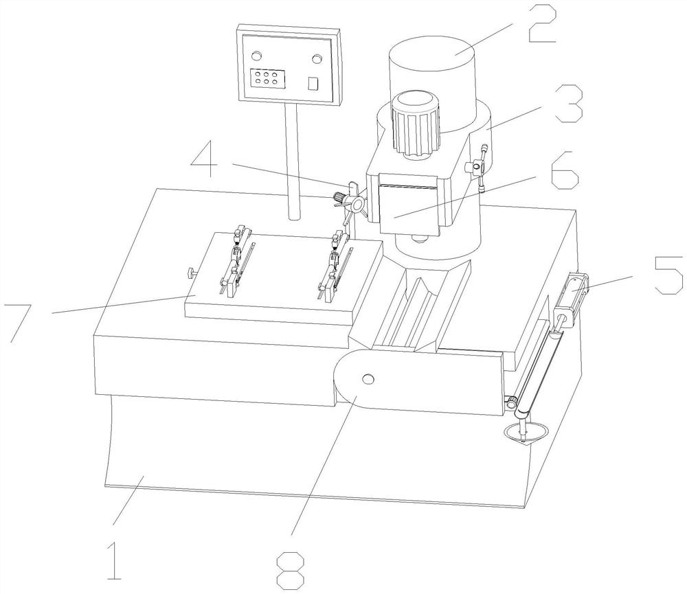
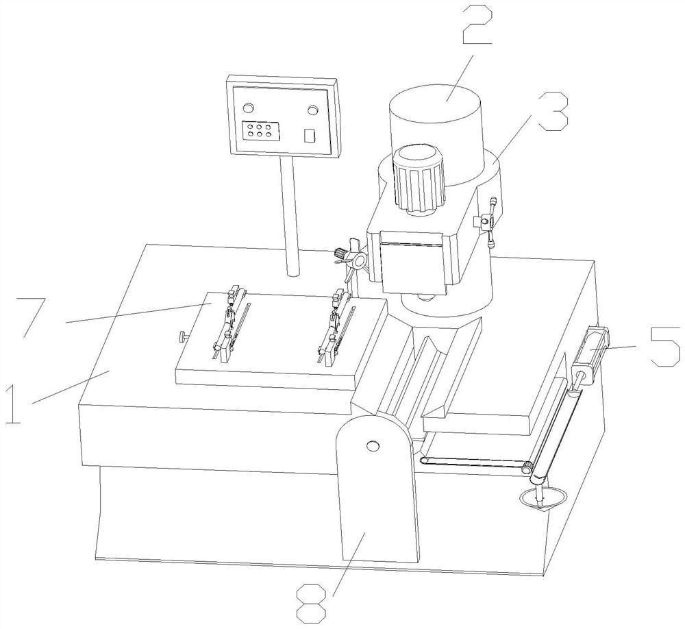
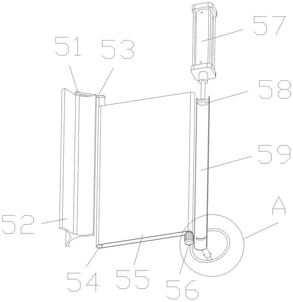
The invention discloses a metal cutting machine tool convenient for collecting chippings, and a using method thereof, and relates to the technical field of cutting machine tool design. The metal cutting machine tool convenient for collecting the chippings comprises a main body, wherein an empty cavity is formed in the main body, a driving rod is fixedly installed on the upper surface of the main body, and a cutting machine head is connected to the outer surface of the driving rod in a sleeved mode; and an electric fan is arranged on the upper surface of the main body, and a chipping removing assembly is arranged on the outer surface of the main body. According to the invention, chippings generated when metal is cut by the cutting machine do not splash all around, the chippings are cleaned through a cleaning assembly, the chippings are prevented from hurting human body and entering the cutting machine, the machining precision is not affected, the abrasion of the cutting machine is reduced, and the service life of the cutting machine is prolonged; and a clamping mechanism of the cutting machine can clamp round and square materials at the same time, the clamping mechanism can be adjusted, the materials of various specifications can be clamped, and a good clamping effect is achieved.

Description

technical field [0001] The invention relates to the technical field of cutting machine tool design, in particular to a metal cutting machine tool for collecting debris and a method for using the same. Background technique [0002] Metal cutting is a method of material removal and forming in the metal forming process. It still occupies a large proportion in today's mechanical manufacturing. The metal cutting process is a process of interaction between the workpiece and the tool. The tool removes excess metal from the workpiece to be processed. And under the premise of controlling productivity and cost, the workpiece can obtain the geometric accuracy, dimensional accuracy and surface quality that meet the design and process requirements, and the metal cutting machine tool can complete this process. [0003] Existing cutting machines will splash a lot of debris when cutting metal. These debris not only harm the human body, but also easily enter the cutting machine. The wear of...

Claims


Application Information

Patent Timeline
Patent Type & Authority Applications(China)
IPC IPC(8): B23Q11/00B23Q3/06
CPCB23Q11/0042B23Q11/005B23Q3/064
Inventor 陈先取
Owner 陈先取
Why Eureka
Try Eureka