Intelligent contact network compensation device for railway

A catenary compensation and intelligent technology, applied in the direction of overhead lines, etc., can solve the problems of small compensation range of catenary loosening and poor working stability, and achieve the effect of improving working stability, increasing service life and increasing compensation effect

Active Publication Date: 2021-11-05
JIANGSU DALICHENG ELECTRICAL
View PDF7 Cites 0 Cited by
  • Summary
  • Abstract
  • Description
  • Claims
  • Application Information

AI Technical Summary

Problems solved by technology

[0004] In view of the above situation, in order to overcome the defects of the prior art, the present invention provides an intelligent catenary compensation device for railways, which effectively solves the problems in the above-mentioned background technology. The problem of poor working stability due to the small range of catenary looseness compensation

Method used


Image

  • Intelligent contact network compensation device for railway
  • Intelligent contact network compensation device for railway
  • Intelligent contact network compensation device for railway

Examples


Embodiment 1

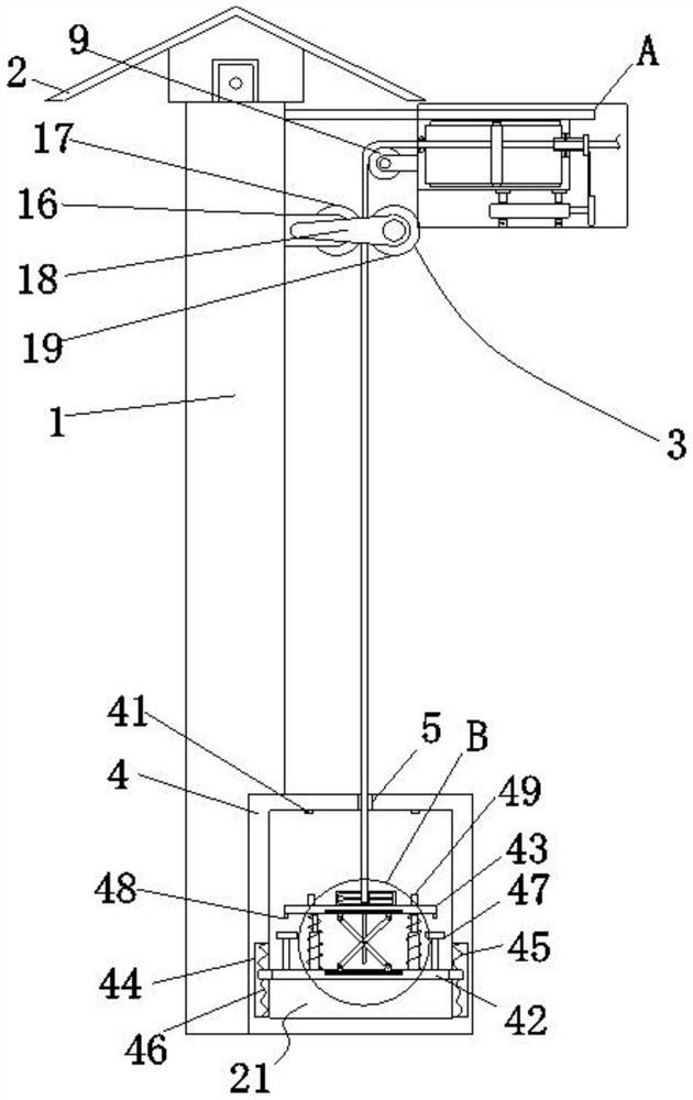
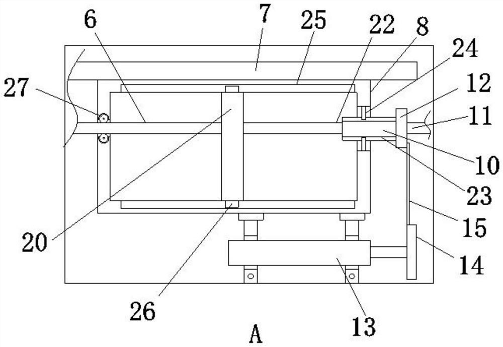
[0032] Embodiment one, by Figure 1 to Figure 5Given, the present invention includes a pole 1, the top of the pole 1 is provided with a photovoltaic panel 2, through the design of the photovoltaic panel 2, it is convenient to receive light and effectively achieve the purpose of energy saving, and the top of one side of the pole 1 is provided with a mounting plate 7. The bottom end of the mounting plate 7 is provided with a compensation box 8, and one side of the vertical rod 1 is provided with a limit group 3 located below the compensation box 8. Through the design of the limit group, the movement stability of the balance rope 6 is improved. One side bottom of the pole 1 is provided with a balance box 4, and the inner top of the balance box 4 is provided with a slot 5, and the inside of the slot 5 runs through a balance rope 6 connected with the limit group 3, and the balance rope 6 is connected to the The tension balance mechanism 21 inside the balance box 4 is connected. By ...

Embodiment 2

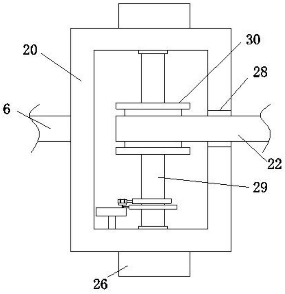
[0036] Embodiment two, on the basis of embodiment one, by image 3 and Figure 4 Given, the lock includes a locking wheel 31, a locking groove 34, a fixed disc 35, an electric push rod 39 and a locking rod 40, the fixed disc 35 is installed on the inner bottom of the connecting box 20, and the rotating shaft 29 is sleeved with a locking The outer wall of the wheel 31 and the locking wheel 31 are equidistantly provided with locking grooves 34, the top of the fixed disc 35 is provided with an electric push rod 39, and the output shaft of the electric push rod 39 is provided with a locking bar 40 extending to the inside of the locking groove 34, The direction stabilizer includes a ratchet 32, a draw-in slot 33, a pawl 36, a stop bar 37 and an engaging spring 38. The ratchet 32 ​​is sleeved on the rotating shaft 29, and the ratchet 32 ​​is located below the locking wheel 31. The outer walls of the ratchet 32 ​​are equidistant from each other. A draw-in groove 33 is provided, and ...

Embodiment 3

[0038] Embodiment three, on the basis of embodiment one, by figure 1 Given, the limit group 3 comprises base 16, pulley one 17, fixed plate 18 and pulley two 19, and base 16 is installed on one side of pole 1, and base 16 is provided with pulley one 17, and base 16 Both sides are symmetrically provided with fixed plates 18, connected by pulley two 19 between two fixed plates 18, and connected by balance rope 6 between pulley one 17 and pulley two 19, by the design of pulley one 17 and pulley two 19, convenient The movable clamping of the balance rope 6 improves the stability of the balance rope 6 , avoids the displacement of the balance rope 6 , and provides convenience for the length compensation and tension balance of the catenary body 11 .


PUM


Abstract

The invention relates to the technical field of electrified railway equipment, discloses an intelligent contact network compensation device for a railway. The invention aims to solve the problem of poor working stability caused by a small loosening compensation range of a contact network. The intelligent contact network compensation device comprises a vertical rod, wherein a photovoltaic panel is arranged at the top end of the vertical rod, a mounting plate is arranged at the top of one side of the vertical rod, a compensation box is arranged at the bottom end of the mounting plate, a limiting set located below the compensation box is arranged on one side of the vertical rod, a balance box is arranged at the bottom of one side of the vertical rod, a first open groove is formed in the inner top end of the balance box, a balance rope connected with the limiting set penetrates through the first open groove, a balance rope is connected with a tension balance mechanism located in the balance box, and a directional wheel connected with the balance rope is arranged on one side of the compensation box. According to the design, the compensation range of the loose length of a contact network body is effectively enlarged, compensation effect is effectively improved, and then the working stability of a contact network is improved.

Description

technical field [0001] The invention belongs to the technical field of electrified railway equipment, in particular to an intelligent catenary compensation device for railways. Background technique [0002] The catenary is a high-voltage transmission line erected above the rails in the electrified railway for the pantograph to take current. The catenary pulley block anchor compensation device includes a movable pulley assembly, a fixed pulley assembly and a weight limit frame, and the catenary pulley block anchor compensation The device is usually installed on the pillars on both sides of the rail, and its main function is to apply rated tension to the catenary cables and contact wires to maintain a constant tension and ensure the pantograph to take power smoothly. [0003] The existing catenary compensation device has a small range of compensation for catenary looseness, and has low compensation performance, which will affect the working stability of the catenary. Content...

Claims


Application Information

Patent Timeline
Patent Type & Authority Applications(China)
IPC IPC(8): B60M1/26
CPCB60M1/26
Inventor 高勇张洪春
Owner JIANGSU DALICHENG ELECTRICAL
Why Eureka
Try Eureka