
Wind turbine blade structure, machining method and applications thereof

A technology of wind turbine blades and blades, which is applied in the field of wind turbine blade structure, and can solve problems such as scrapped blades, hidden dangers of blade strength, and increased blade costs

Inactive Publication Date: 2011-11-09
黄争鸣
View PDF0 Cites 1 Cited by
  • Summary
  • Abstract
  • Description
  • Claims
  • Application Information

AI Technical Summary

Problems solved by technology

[0008] The disadvantage of the second type of end punching type is that blade manufacturers must purchase expensive punching devices (currently, a set of devices that can punch holes at the end of 1.5MW fan blades is generally not less than 2 million yuan), equipped with special punching workshop
Given that large blades are bulky, these inputs increase blade cost
Moreover, the transverse perforation partially cuts off the continuity of the fiber layup, which brings hidden dangers to the strength of the blade.
Other disadvantages include the difficulty in determining the position of the initial longitudinal hole, the difficulty in ensuring concentricity between the longitudinal hole and the horizontally inserted nut hole, and even the blade being scrapped due to improper drilling

Method used


Image

  • Wind turbine blade structure, machining method and applications thereof
  • Wind turbine blade structure, machining method and applications thereof
  • Wind turbine blade structure, machining method and applications thereof

Examples


Embodiment 1

[0101] A 38m long blade, the main beam design is composed of unidirectional glass fiber cloth reinforced epoxy resin composite material, the main beam width is 310mm, the single layer cloth thickness is 0.9mm, and the density is 1950kg / m 3 , the thickest layer is 50 layers. I 1 =2354062.5mm 4 , the moment of inertia generated in the shimmy direction (perpendicular to the blade axis) is I 2 =111716250mm 4 .

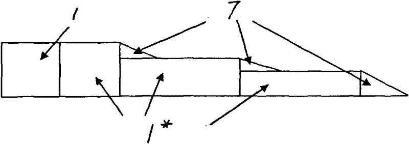
[0102] Now, the specific gravity is 60kg / m 3 The PVC foam material is pre-processed into Figure 9 The trapezoidal column shown, the upper bottom width of the trapezoidal column (wedge column 1') b=105mm, the included angle θ=60°, and the column height h=50mm. Based on this, the lower bottom width of the trapezoidal column is calculated to be 162.7mm. Column 1' is combined with unidirectional fabric wrapping identical to the current design Figure 10 The section shown, wherein, the bottom layer 2' (bottom fiber cloth), inner cladding layer 3' (inner fiber cloth) and...

Embodiment 2

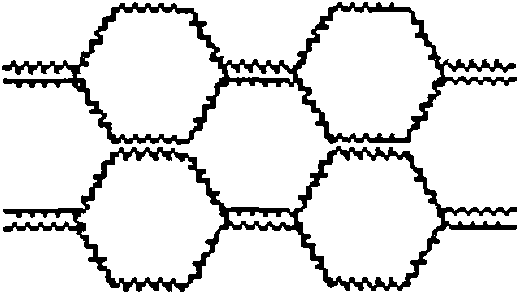
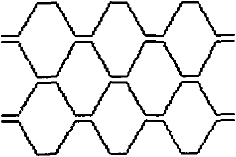
[0105] For the main beam structure of the blade in the above-mentioned embodiment 1, a 3mm thick axial bamboo sliced ​​slat is adopted, the slat width is 160mm, and the slat axial modulus of elasticity E 1 =12GPa, its specific gravity ρ=800kg / m 3 ,according to Figure 6h Bonding shown, the interior angle of the triangular wedge 1" is 60°, resulting in Figure 16 The honeycomb cell cross-section beam shown has the same beam length as the main beam of the thickest section of the blade, and is closed at both ends. According to the geometric dimensions of the given section, it is not difficult to calculate the moment of inertia in the waving direction of the section as I′ 1 =15672897.3mm 4 , The moment of inertia in the shimmy direction is I′ 2 =100882233.3mm 4 . When used as the main beam of the blade, lay two layers of unidirectional cloth on the bottom skin layer foundation, that is, the bottom layer is 2” (bottom fiber tape), and the thickness of the single layer is 0.9m...

Embodiment 3

[0108] The outer diameter of the root circle of a 38m-long blade is D=1890mm, the root circle is 1m long, including the embedded bolt sleeve at the root, and the weight of the 1m-long blade section at the root is 888kg. The bending stiffness distribution along the two orthogonal axes is shown in Figure 11 (marked as the current structure in the figure).

[0109] The design of the blade root section of the present invention is described as follows.

[0110] 1. Raw materials (0° direction along the blade axis)

[0111] (1) Triaxial cloth [+45° / 0° / -45°], single-layer thickness 0.87mm, after RIM dipping, the modulus of elasticity along the axial direction of the blade is E=25.5GPa, density=1950kg / m 3 , code A;

[0112] (2) Unidirectional fabric [0°], single layer thickness 0.9mm, elastic modulus E along blade axial direction after RIM dipping 1 =39.5GPa, transverse elastic modulus E 2 =14GPa, shear modulus G 12 =14GPa, Poisson's ratio μ 12 = 0.21, density = 1950kg / m 3 , co...


PUM

PropertyMeasurementUnit
densityaaaaaaaaaa
elasticityaaaaaaaaaa
elastic modulusaaaaaaaaaa

Abstract

The invention relates to a wind turbine blade structure, a processing and forming method and applications thereof. The blade consists of a root segment, a main beam and a covering that wraps the root segment and the external side of the main beam; the blade is fixed with a wind wheel by a connecting piece that is arranged at the root segment, thus forming a spatial cantilever beam structure; at the main beam area and the root segment, one or more solid or hollow wedge-shaped columns are arranged between a top paving layer and a bottom paving layer; the wedge-shaped column at the internal-mostside of the root end is solid and is internally provided with the connecting piece, wherein the fiber cloth is arranged at least among the adjacent wedge-shaped columns at the internal-most side of the root segment and continuously intersects and enwinds the wedge-shaped columns in a horizontal S-shaped, thus forming an interlayer; and the top paving layer, the bottom paving layer and the fiber cloth interlayer are dipped and solidified to form a framework with a honeycomb-shaped section. The structure and the method have the advantages of: leading the once pouring of resin and once solidifying and forming for the large blade and the realizing of the pre-embedding of the connecting piece of the root part to be possible, dispersing the synergistic effect and solidifying shrinkage quantity of solidified heating of the bottom paving layer and the top paving layer by the wedge-shaped columns, and leading the unsaturated resin used as a substrate material to be possible.

Description

technical field [0001] The invention relates to a wind turbine blade structure, and the way to realize the structure by using different materials, the processing molding method and the application. Background technique [0002] The shortage of fossil energy will eventually lead to depletion, prompting countries all over the world to vigorously develop renewable wind energy. The way to achieve it is to use the wind wheel to drive the wind wheel to rotate, and drive the wind turbine to generate electricity or do mechanical work, that is, to convert the kinetic energy of the wind into electrical energy or mechanical energy. A wind wheel usually consists of several blades. Since the output power of a wind turbine is proportional to the surface area of ​​the blade and also proportional to the cube of the wind speed, the blades of a high-power wind turbine are often very large. The blade length of a 1.5MW (megawatt) wind turbine with a rated wind speed of 11m per second is gener...

Claims


Application Information

Patent Timeline
Patent Type & Authority Patents(China)
IPC IPC(8): F03D1/06B29C70/34B29C70/54
CPCY02E10/72F03D1/0675B29L2031/085Y02E10/721Y02P70/50
Inventor 黄争鸣
Owner 黄争鸣
Learn More