
Aviation aircraft environment control system humidity control device maintenance method

A control system and humidity control technology, applied in aircraft maintenance, aircraft parts, transportation and packaging, etc., can solve problems such as the impact of the entire aircraft maintenance and support work, unfavorable combat training and combat effectiveness, and wire mesh B222 holes. The effect of enhancing the comprehensive support capability of equipment, improving the timeliness of equipment delivery, and enhancing operability

Pending Publication Date: 2021-11-05
芜湖天航装备技术有限公司
View PDF0 Cites 0 Cited by
  • Summary
  • Abstract
  • Description
  • Claims
  • Application Information

AI Technical Summary

Problems solved by technology

The welding process is quite difficult, and the welding temperature is too high. The wire mesh structure of wire mesh A221 and wire mesh B222 may be burnt or severely oxidized, resulting in a very low yield
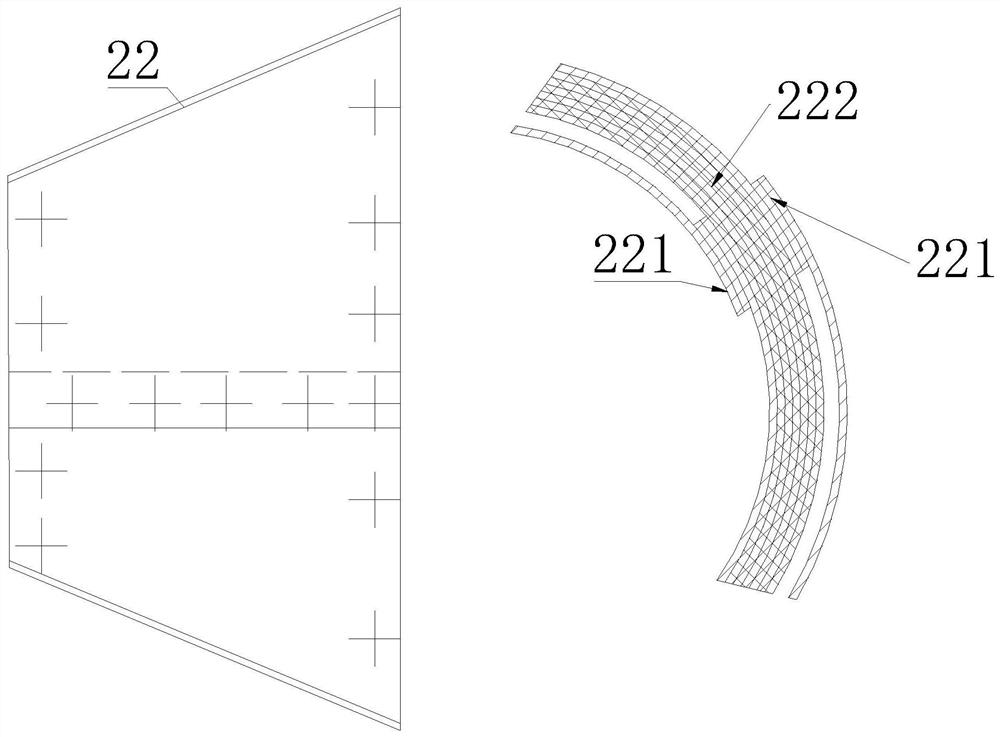
Secondly, because the upper limit of the air flow through the water eliminator exceeds 2000kg / h, under the complex operating environment of the aircraft, the coalescer often has failures such as desoldering of the wire mesh A221, holes, and thus holes in the wire mesh B222
When the damaged condenser 2 is returned to the support unit for maintenance, the seemingly simple structure is difficult to carry out maintenance
Frequent failures, processing and maintenance difficulties and other factors have seriously affected the maintenance and support of the entire aircraft, which is not conducive to combat training and combat effectiveness

Method used


Image

  • Aviation aircraft environment control system humidity control device maintenance method
  • Aviation aircraft environment control system humidity control device maintenance method
  • Aviation aircraft environment control system humidity control device maintenance method

Examples


Embodiment Construction

[0046] In order to make the technical means, creative features, goals and effects achieved by the present invention easy to understand, the present invention will be further elaborated below in conjunction with the accompanying drawings and embodiments.

[0047] like Figure 1 to Figure 9 Shown, a kind of air vehicle environmental control system humidity control device maintenance method, concrete steps are as follows:

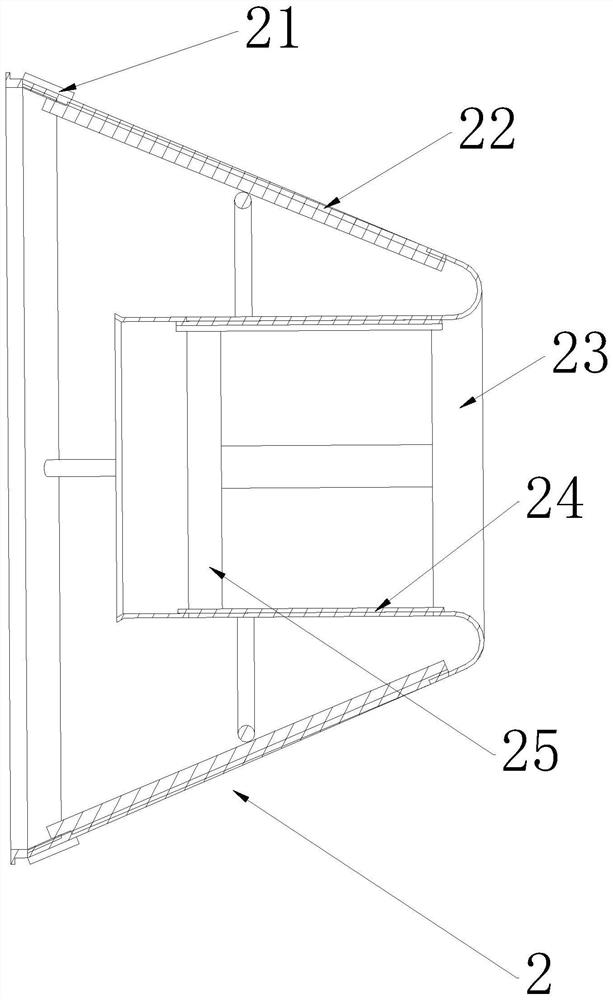
[0048] (1) Reference figure 2 , Remove the liner A21 and liner B25 on the condenser 2.

[0049] (2) Reference figure 1 and figure 2 , take off the cone net 22 and the cylinder net 24 with a polishing machine, and grind and polish the welding spot positions of the flange 236 and the fairing 231. To facilitate re-welding after maintenance.

[0050] (3) Use the stainless steel strip with the same material and thickness as the wire mesh A221, cut out the sheet metal parts A and B with an expansion angle of 180°, corresponding outer diameters of 182.32mm and...


PUM


Abstract

The invention relates to the technical field of aviation aircraft humidity control device maintenance, in particular to an aviation aircraft environment control system humidity control device maintenance method which comprises the following specific steps: removing a liner A and a liner B on a coagulator; taking down a conical net and a cylindrical net through a polishing machine, and grinding and polishing the welding spot positions of the flange and the fairing; machining a stainless steel band with the same material and thickness as the silk screen A into a part A and a part B; machining a stainless steel band which is made of the same material as the silk screen A and has the thickness of 0.71 mm into a part C and a part D; utilizing a stainless steel band with the thickness of 0.45 mm to be machined into a strip E with the width of 8 mm. The problems that the silk screen welding process is poor and the yield is low are solved; the welding operability is enhanced, and the manufacturability is improved; the flow characteristic of the product before and after maintenance still meets the product specification requirement; additional operation equipment is not needed, and the implementation cost is low; and the equipment delivery timeliness is improved, and the comprehensive guarantee capability of the equipment is enhanced.

Description

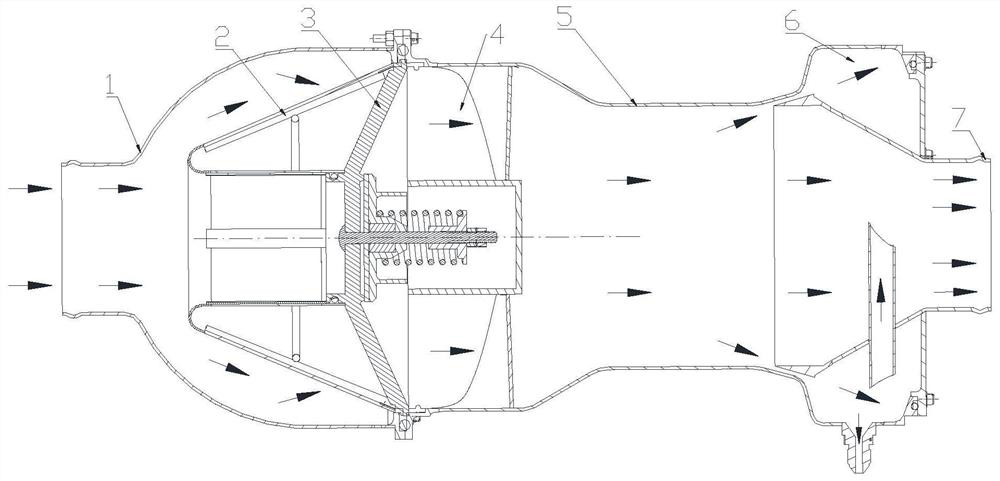
technical field [0001] The invention relates to the technical field of maintenance of humidity control devices of aviation aircraft, in particular to a maintenance method of humidity control devices of the environmental control system of aviation aircraft. Background technique [0002] At present, the environmental control system of both civil aircraft and military aircraft is still based on the air circulation system. The water eliminator is the main humidity control device of this type of environmental control system. During the operation of the whole system, the main function of the water eliminator is to separate the free-state water micro-groups that have condensed into large particles from the high-speed airflow, ensuring that the cockpit Supply air humidity requirements for pilot comfort and electronics bay cooling. [0003] At present, a military aircraft environmental control system uses a water eliminator (such as figure 1 As shown), it is composed of inlet pipe ...

Claims


Application Information

Patent Timeline
Patent Type & Authority Applications(China)
IPC IPC(8): B64F5/40B64D13/06
CPCB64F5/40B64D13/06B64D2013/0662
Inventor 薛继鹏齐慧英刘锐班超王亚龙罗雁宋冬乐婷张睿
Owner 芜湖天航装备技术有限公司
Learn More