Multistage rectification slideway vertical shaft rotational flow flood discharge tunnel

A technology for flood discharge tunnels and flow channels, which is applied in water conservancy projects, sea area projects, coastline protection, etc., to achieve the effects of slowing down the flow velocity, avoiding the accumulation of sand and gravel, and avoiding the accumulation of sand and gravel

Inactive Publication Date: 2021-11-05
HUBEI PROVINCIAL WATER RESOURCES & HYDROPOWER PLANNING SURVEY & DESIGN INST
View PDF12 Cites 1 Cited by
  • Summary
  • Abstract
  • Description
  • Claims
  • Application Information

AI Technical Summary

Problems solved by technology

[0003] The purpose of the present invention is to solve the shortcomings of the above-mentioned background technology, and provide a multi-stage rectification slide shaft swirl flood discharge tunnel, which solves the problems of the existing flood discharge tunnels, has a simple structure and is easy to operate

Method used


Image

  • Multistage rectification slideway vertical shaft rotational flow flood discharge tunnel
  • Multistage rectification slideway vertical shaft rotational flow flood discharge tunnel
  • Multistage rectification slideway vertical shaft rotational flow flood discharge tunnel

Examples


Embodiment Construction

[0030] Embodiments of the present invention are described in detail below, wherein the same or similar reference numerals represent the same or similar elements or elements having the same or similar functions. The embodiments described below by referring to the figures are exemplary and are intended to explain the present invention and should not be construed as limiting the present invention.

[0031] In describing the present invention, it should be understood that the terms "longitudinal", "transverse", "length", "width", "thickness", "upper", "lower", "front", "rear", " The orientation or positional relationship indicated by "left", "right", "vertical", "horizontal", "top", "bottom", "inner" and "outer" are based on the orientation or positional relationship shown in the drawings, and only It is for the convenience of describing the present invention and simplifying the description, but does not indicate or imply that the device or element referred to must have a specific...


PUM


Abstract

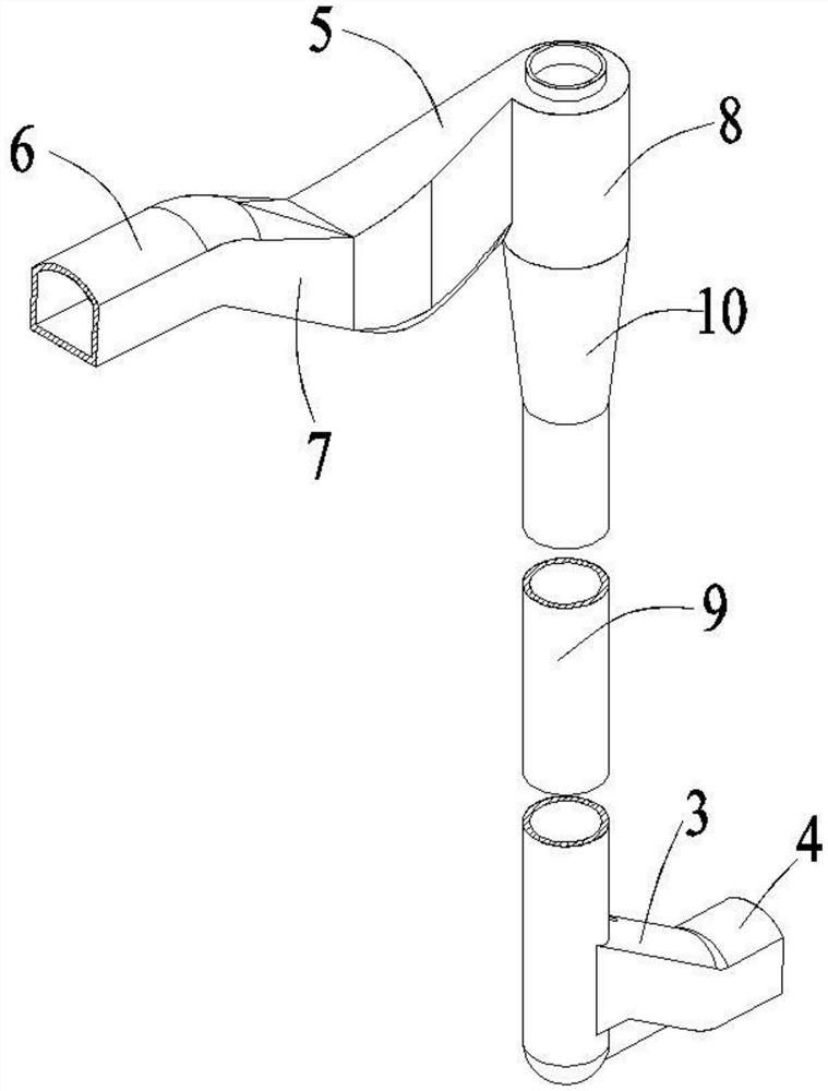
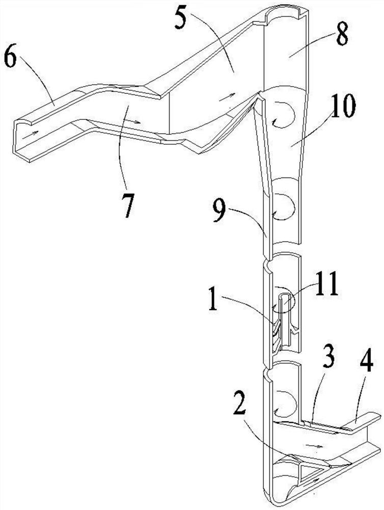
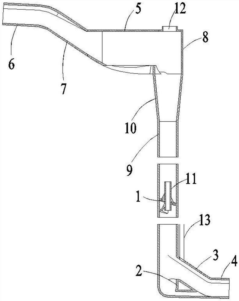
The invention relates to the technical field of rotational flow energy dissipation structures in the technical field of vertical shaft drop energy dissipation structures, and particularly relates to a multistage rectification slideway vertical shaft rotational flow flood discharge tunnel. The multistage rectification slideway vertical shaft rotational flow flood discharge tunnel comprises a straight inlet section, a straight outlet section and a vertical flow channel, wherein the upper end of the vertical flow channel is connected with the straight inlet section, and the lower end of the vertical flow channel is connected with the straight outlet section; a plurality of sets of spiral slideways enabling water flow in the vertical flow channel to flow downwards in a winding mode in the tangential direction of the inner wall of the flow channel are arranged in the vertical flow channel and are arranged at intervals in the vertical direction; and an overflow structure is arranged in the straight outlet section and suspended in the center of the flow channel of the straight outlet section to divide the flow channel of the straight outlet section into a fluid circulation flow channel above the overflow structure and a fluid sand washing flow channel below the overflow structure. The flood discharge tunnel is simple in structure, the flow speed of fluid can be greatly decreased through the arranged multistage spiral slideways, a good energy dissipation effect is achieved on the fluid, and the problems of sand and stone accumulation and overflow water recession can be effectively solved through the arranged overflow structure.

Description

technical field [0001] The invention relates to the technical field of vertical shaft swirling flow energy dissipation structures, in particular to a multi-stage rectifying slideway vertical shaft swirling flood discharge tunnel. Background technique [0002] As a relatively new type of energy dissipation engineering facility, the swirl shaft spillway tunnel has been used in water conservancy and hydropower projects with relatively low water head, especially because of its flexibility to easily realize the plane turning of the spillway tunnel, it is more and more popular. Welcome, in recent years, there has been a tendency to gradually popularize and apply it to high-head water conservancy and hydropower projects. For example, the patent No. "CN202110103582.6" is a Chinese invention patent named "A Rotary Stilling Pool Energy Dissipation Structure Suitable for Vertical Shafts". The energy dissipation structure introduced in this patent includes a water inlet section, a shaft...

Claims


Application Information

Patent Timeline
Patent Type & Authority Applications(China)
IPC IPC(8): E02B8/06B08B3/02
CPCE02B8/06B08B3/02
Inventor 谌伟宁杨佳刚徐大朋潘亚辉熊卫红李海涛
Owner HUBEI PROVINCIAL WATER RESOURCES & HYDROPOWER PLANNING SURVEY & DESIGN INST
Why Eureka
Try Eureka