High-pressure turbine moving blade set with damping vibration attenuation blocks

A high-pressure turbine and damping block technology, applied in the direction of engine components, machines/engines, blade support components, etc., can solve problems that affect the life and safety and reliability of gas turbines, high-cycle fatigue fracture of blades, and forced vibrations, etc. , to achieve good vibration damping effect, improve service life, simple and reliable structure

Pending Publication Date: 2021-11-05
中国船舶重工集团公司第七0三研究所
View PDF6 Cites 4 Cited by
  • Summary
  • Abstract
  • Description
  • Claims
  • Application Information

AI Technical Summary

Problems solved by technology

[0005] The purpose of the present invention is to solve the problem that the existing high-pressure turbine rotor blades of gas turbines are prone to forced vibration under the excitation of air flow force, and the high-cycle fatigue fracture of the blades will affect the life and safety and reliability of the gas turbine. It provides a High pressure turbine bucket set with damping block

Method used


Image

  • High-pressure turbine moving blade set with damping vibration attenuation blocks
  • High-pressure turbine moving blade set with damping vibration attenuation blocks
  • High-pressure turbine moving blade set with damping vibration attenuation blocks

Examples


Embodiment 1

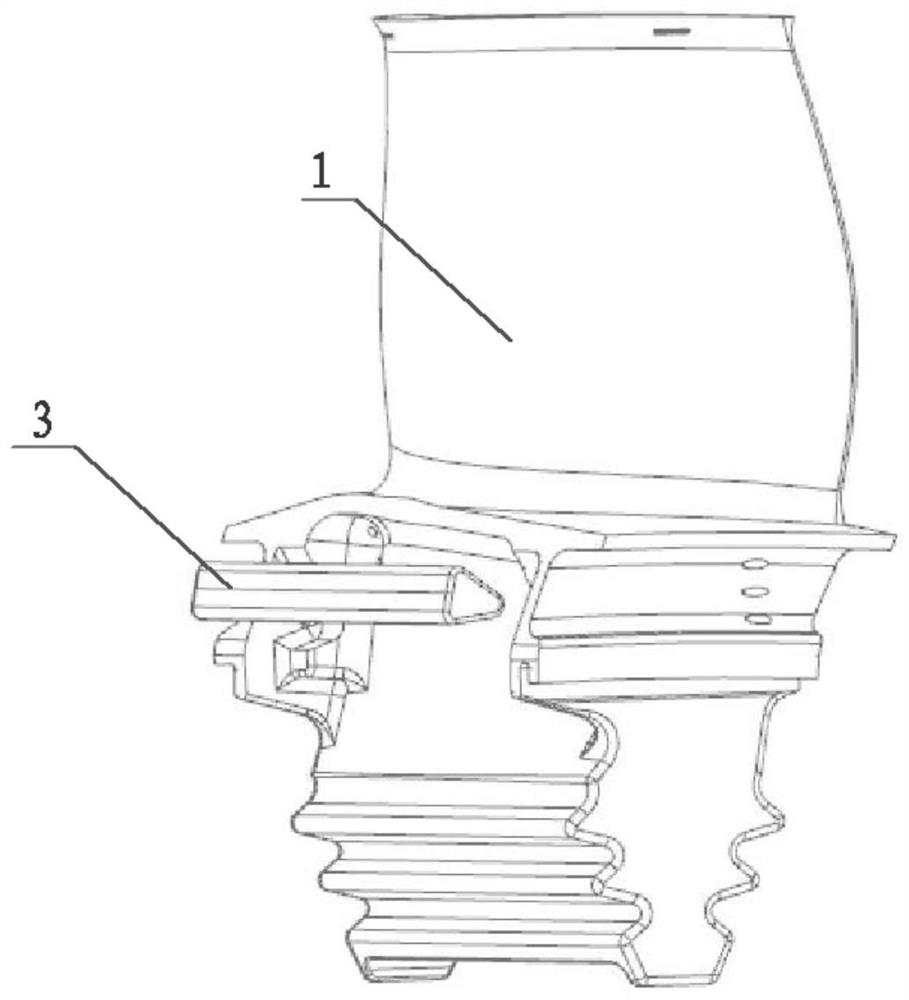
[0031] combine Figure 4 and Figure 7 , there is a first boss 1-10 and a second boss 1-11 at the root of the first high-pressure turbine blade 1 blade back side, the geometric dimensions of the two bosses are equal, and they are used for the positioning of the damping block 3 to prevent The damping damping block 3 falls off. combine Figure 8 , The damping and vibration-absorbing block 3 is a prism-shaped solid structure.

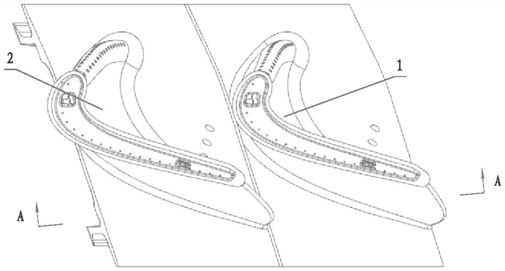
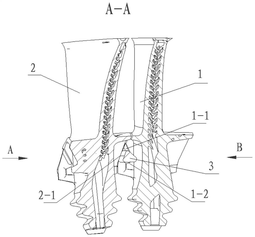
[0032] combine Figure 1 to Figure 8 , the front surface 1-1 and the rear surface 1-4 of the lower edge plate on the back side of the first high-pressure turbine blade 1 form a certain angle with the blade along the blade height direction; the blade basin side of the second high-pressure turbine blade 2 The surface 2-1 of the lower edge plate forms a certain angle with the blade along the blade height direction. The first surface 1-1 and the second surface 1-2 of the lower edge plate on the back side of the first high-pressure turbine blade 1 form the...

Embodiment 2

[0034]The first high-pressure turbine blade 1 and the second high-pressure turbine blade 2 have the same structure, and both are blades without shrouds and have complex cooling structures.

Embodiment 3

[0036] combine Figure 5 to Figure 8 , there is a circular gap of R15 in the damping block 3, the size of which is designed according to the specific shape of the extension root 1-7 on the back side of the first high-pressure turbine blade 1, which can ensure that the damping block 3 and the extension There is a certain gap between the roots 1-7 to ensure the smooth flow of the cooling air and prevent the damping and shock absorbing block 3 and the extension roots 1-7 from being squeezed during the working process.


PUM


Abstract

The invention belongs to the technical field of gas turbine equipment and particularly relates to a high-pressure turbine moving blade set with damping vibration attenuation blocks. According to the high-pressure turbine moving blade set with the damping vibration attenuation blocks, the damping vibration attenuation blocks are arranged in cavities between adjacent high-pressure turbine moving blade extending roots, when an engine works, the damping vibration attenuation blocks rotate along with high-pressure turbine moving blades, the centrifugal force generated by the damping vibration attenuation blocks provides normal stress for friction contact between the damping vibration attenuation blocks and the high-pressure turbine moving blades, and when the blades vibrate, the vibration quantity is consumed through contact friction between the blades and the damping vibration attenuation blocks, so that the vibration stress is reduced. The high-pressure turbine moving blade set is simple and reliable in structure, good in vibration attenuation effect, easy and convenient to regulate and control, high in environmental adaptability and free of influences of an engine temperature field and a flow field, structural parameters of the high-pressure turbine blades do not need to be greatly changed, blade damping can be effectively increased, the safety margin of working of the high-pressure turbine moving blades is increased, the service life of the turbine blades is prolonged, and the gas turbine safe operation reliability is improved.

Description

technical field [0001] The invention belongs to the technical field of gas turbine equipment, and in particular relates to a high-pressure turbine moving blade group with damping and vibration-absorbing blocks. Background technique [0002] Gas turbines are complex and sophisticated high-tech products, known as the "crown jewel" of the manufacturing industry. With the development of modern gas turbine technology, the inlet temperature of gas turbine turbine continues to increase, and the working environment of turbine blades becomes more and more severe. High-pressure turbine rotor blades work in a high-temperature, high-pressure, and high-speed rotating environment, and bear the centrifugal force brought by their own high-speed rotation, the aerodynamic force generated by the impact of mainstream gas, and the thermal stress caused by the uneven temperature field distribution of the blade itself. During the working process, the aerodynamic pressure on the surface of the bla...

Claims


Application Information

Patent Timeline
Patent Type & Authority Applications(China)
IPC IPC(8): F01D5/26F01D5/18
CPCF01D5/26F01D5/18
Inventor 霍玉鑫姜爽李宗全侯隆安黎明牛夕莹卫嘉李涛
Owner 中国船舶重工集团公司第七0三研究所
Why Eureka
Try Eureka