
Calculation method and system for alternating current power flow model of radial power distribution network

A technology of AC power flow and power distribution system, applied in computing, computer-aided design, and AC networks with the same frequency from different sources, etc., can solve problems such as unsatisfactory, high-proportion access to distributed power supply complex and changeable, and achieve The effect of improving universality

Active Publication Date: 2021-11-05
SHANGHAI JIAO TONG UNIV
View PDF7 Cites 2 Cited by
  • Summary
  • Abstract
  • Description
  • Claims
  • Application Information

AI Technical Summary

Problems solved by technology

Although this existing technology makes up for the shortcomings of the existing distributed power supply maximum access capacity calculation model, such as poor data model privacy and potential numerical stability problems, it cannot solve the complex and changeable problems caused by the high proportion of distributed power access. It cannot meet the needs of real-time monitoring and dispatching of large-scale distributed power sources and the operation of electricity sales transactions in the renewable energy market, and develops technical problems for fast and accurate calculation of power flow status at the distribution side

Method used


Image

  • Calculation method and system for alternating current power flow model of radial power distribution network
  • Calculation method and system for alternating current power flow model of radial power distribution network
  • Calculation method and system for alternating current power flow model of radial power distribution network

Examples


Embodiment Construction

[0107] The present invention will be described in detail below in conjunction with specific embodiments. The following examples will help those skilled in the art to further understand the present invention, but do not limit the present invention in any form. It should be noted that those skilled in the art can make several changes and improvements without departing from the concept of the present invention. These all belong to the protection scope of the present invention.

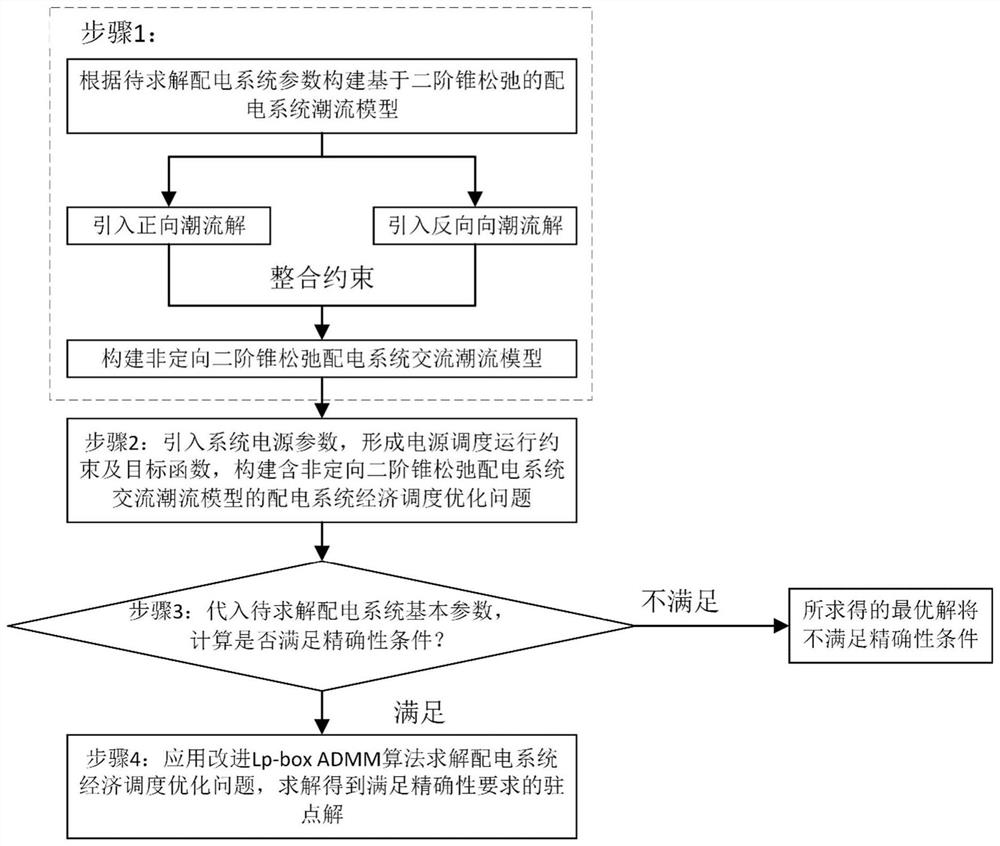
[0108] A calculation method for an AC power flow model of a radial distribution network provided by the present invention comprises the following steps:

[0109] Step S1: According to the second-order cone power flow model of the power distribution system under the predefined power flow path, list the feasibility constraints describing the characteristics of the bidirectional feeder power flow solution, and introduce the binary direction variable to limit the uniqueness of the final power flow solution, ...


PUM


Abstract

The invention provides a calculation method for an alternating current power flow model of a radial power distribution network, which comprises the following steps of: S1, constructing a non-directional second-order cone relaxation radial power distribution network alternating current power flow model for eliminating a predefined power flow path requirement according to a second-order cone power flow model of a power distribution system; s2, describing a radial power distribution network power flow state according to the non-directional second-order cone relaxation radial power distribution network alternating current power flow model, and constructing a power distribution system economic dispatching optimization model with a mixed integer quadratic programming structure; s3, judging whether the system, connected with the high-proportion distributed power supply, in the step S2 meets a given beforehand sufficiency condition or not, and determining that a power flow solution obtained by the constructed economic dispatching optimization model of the power distribution system can meet operation requirements; and S4, for the power distribution system economic dispatching optimization model of which the obtained power flow solution can meet the operation requirement, performing parallel calculation by using an improved Lp-box alternating direction multiplier method. According to the method, the problem of quickly solving the alternating current power flow state of the power distribution system connected with the high-proportion distributed power supply can be effectively solved.

Description

technical field [0001] The present invention relates to the technical field of power system power flow models, in particular to a calculation method and system for an AC power flow model of a radial distribution network, and in particular to a calculation method for an AC power flow model of a non-directional second-order cone-relaxed radial distribution network methods and systems. Background technique [0002] The widespread access of a high proportion of distributed power poses challenges to the safe and stable operation of power distribution systems. In order to ensure the safety and economy of the power distribution system in the operating environment of highly uncertain source and load, and to meet the needs of real-time monitoring and dispatching of large-scale distributed power sources and the operation of electricity sales transactions in the renewable energy market, the development of fast and accurate calculation of power distribution side The distribution networ...

Claims


Application Information

Patent Timeline
Patent Type & Authority Applications(China)
IPC IPC(8): G06F30/20H02J3/06G06F113/04
CPCG06F30/20H02J3/06H02J2203/10H02J2203/20G06F2113/04Y04S10/50
Inventor 黄淳驿王承民谢宁
Owner SHANGHAI JIAO TONG UNIV
Learn More