Knob operation assembly and household appliance

A technology of knobs and components, which is applied in the direction of circuits, electric switches, electrical components, etc., can solve the problems of increasing the design gap, shaking of the knob operation components, and not effectively solving the shaking of the matching parts of the knob structure.

Pending Publication Date: 2021-11-05
PANASONIC APPLIANCES CHINA CO LTD +1
View PDF1 Cites 0 Cited by
  • Summary
  • Abstract
  • Description
  • Claims
  • Application Information

AI Technical Summary

Problems solved by technology

[0004] However, this utility model does not effectively solve the shaking of the matching part of the knob structure, and there is still a large shaking when the user operates the knob operation assembly. Large, mainly caused by two factors: 1. In this patent, through the radial limit operation knob of the peripheral wall unit, in actual assembly, it is difficult to achieve a perfect zero-distance fit between the two parts, and there are assembly tolerances. In this patent, The first assembly tolerance needs to be reserved when the encoder is matched with the back hole of the substrate support member, and the second assembly tolerance needs to be reserved when the inner peripheral surface of the peripheral wall unit is matched with the cylindrical part of the action shaft unit. Therefore, after actual assembly, if you want to realize the If the coaxiality between the unit and the encoder is matched, the limit gap between the peripheral wall unit and the cylindrical part of the action shaft unit must be enlarged, which is actually the accumulation of the first assembly tolerance and the second assembly tolerance
2. The action shaft of the operating knob is fully wrapped with the encoder rod. There is a tolerance deviation between the encoder rod and the encoder base in the axial direction. When the operating knob is assembled on the encoder rod, due to the wrapped The fixed way causes the concentricity of the operating knob relative to the encoder to be greatly affected by the tolerance of the rod part, which leads to a further increase in the design gap when designing the limit gap between the peripheral wall unit and the cylindrical part of the action shaft unit, considering the influence of this factor. As a result, the knob operation component shakes a lot during use, and the all-enveloping fit is not easy to install

Method used


Image

  • Knob operation assembly and household appliance
  • Knob operation assembly and household appliance
  • Knob operation assembly and household appliance

Examples


Embodiment 1

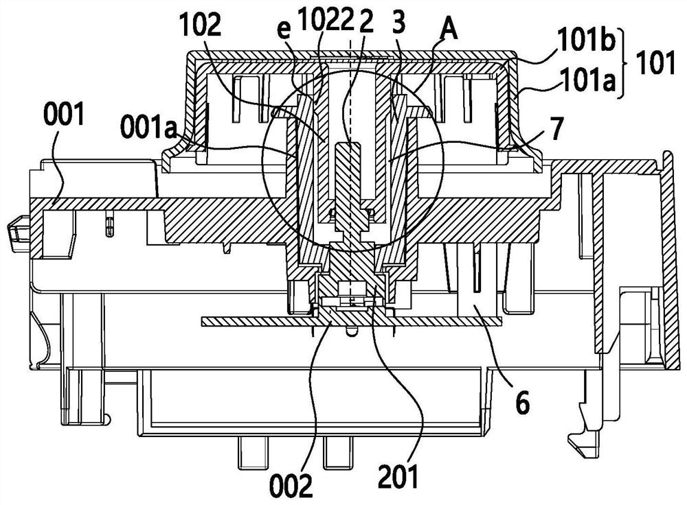
[0054] like Figure 1 to Figure 5 As shown, the knob operates components, including:

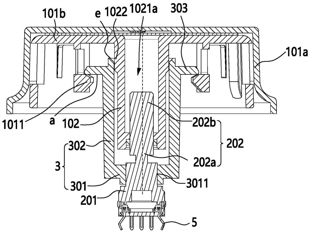
[0055] operating knob 1; and

[0056] The encoder 2 has a base 201 and a rotating shaft 202 connected to the base 201, the operation knob 1 drives the rotating shaft 202 to act synchronously, and the base 201 generates a corresponding electrical signal in response to the action of the rotating shaft 202; and,

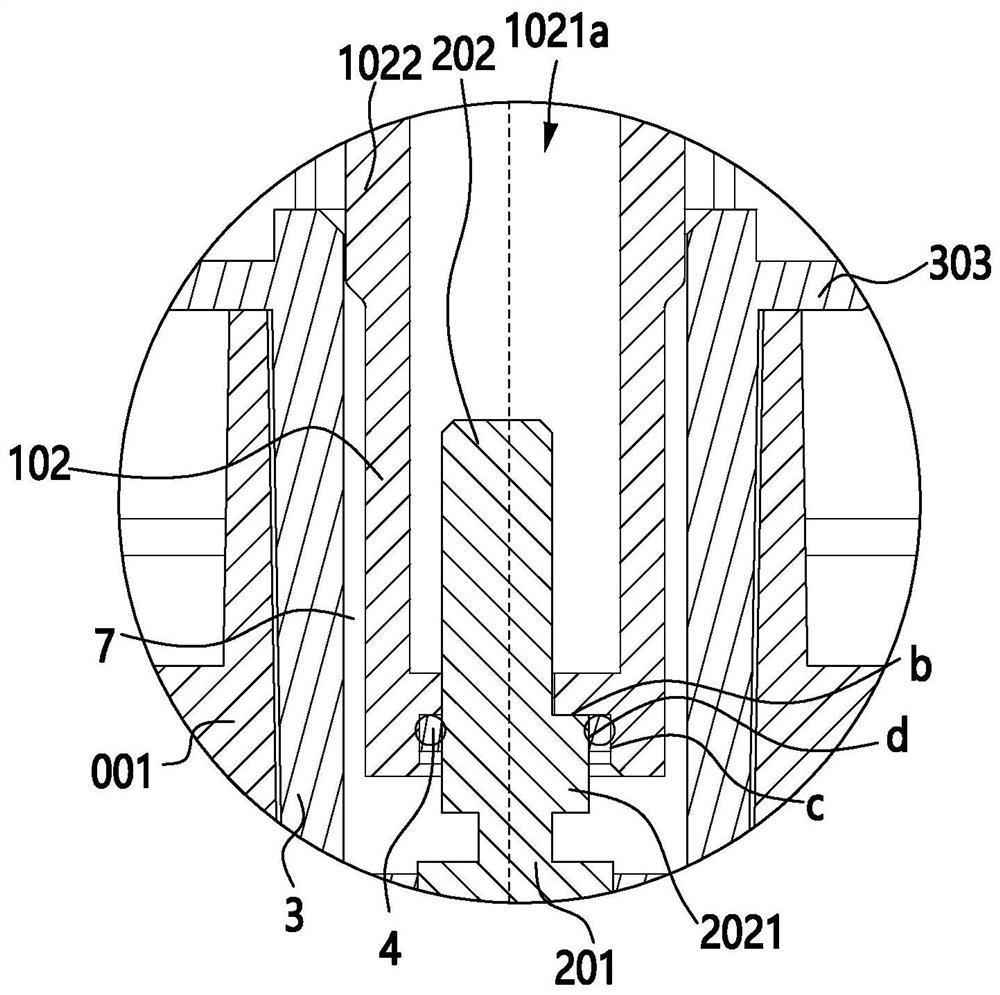
[0057] The limiting member 3 connected with the base 201 is used for radially limiting the operating knob 1 .

[0058] Based on the problem that the encoder knob shakes due to the cumulative tolerance problem in the prior art, the solution proposed by the present invention is to connect the limit member 3 for the radial limit operation knob 1 to the base 201 of the encoder 2, in other words , the encoder indirectly radially limits the operating knob 1 through the limiter 3, since the limiter 3 is connected to the base 201 of the encoder 2 to form an assembly, and the fit tolerance b...

Embodiment 2

[0076] like figure 1 with Figure 5 As shown, the household appliance includes an operation panel 001 on which the knob operation assembly in the first embodiment is installed.

[0077] Specifically, such as figure 1 As shown, the operation panel 001 is provided with an assembly hole 001a for installing the rotating shaft 202 and the stopper 3, the operation knob 1 is located on the outside of the operation panel 001, and the inside of the operation panel 001 is provided with a circuit board 002 electrically connected to the base 201 .

[0078] With the above structure, when assembling, such as Figure 5 As shown, the base 201 of the encoder 2 is first installed on the circuit board 002 through the pin 5, and then the rotating shaft 202 of the encoder 2 is inserted into the assembly hole 001a of the operation panel 001, and the circuit board 002 and the operation panel 001 pass through The screw 6 is fixedly connected by means of penetration, etc., and then the limiter 3 i...


PUM


Abstract

The invention discloses a knob operation assembly and a household electrical appliance, and belongs to the technical field of household electrical appliances. The knob operation assembly comprises an operation rotary knob; an encoder which is provided with a base and a rotating shaft connected to the base, wherein the rotating shaft is driven by the operation knob to synchronously act, and the base responds to the action of the rotating shaft to generate a corresponding electrical signal; a limiting member which is connected with the base and used for radially limiting the operation knob, wherein the encoder indirectly and radially limits the operation knob through the limiting member, the limiting member is connected to the base of the encoder to form an assembly, and the limiting member and the base can keep good coaxiality; moreover, the fit tolerance between the limiting piece and the operation knob is not limited by the assembly tolerance of other parts, so the fit tolerance between the limiting piece and the operation knob can be reduced as much as possible on the premise of not influencing the action of the operation knob, the shaking feeling of the operation knob is reduced, and the operation experience is improved.

Description

【Technical field】 [0001] The invention relates to the technical field of household appliances, in particular to a knob operation assembly and household appliances. 【Background technique】 [0002] With the improvement of living standards, people's pursuit of household appliances is getting higher and higher, hoping to quickly and accurately set the mode they need. The operation of many household appliances is realized through knob operation components, but the existing knob operation components Due to component processing errors and assembly methods, there is a problem of large shaking. [0003] In order to improve the above deficiencies, an operating assembly is disclosed in the utility model patent document of the authorized announcement number CN207987546U, which is called the operating assembly and the laundry treatment device equipped with the operating assembly, which includes an operating knob, a peripheral wall unit, a substrate supporting member, The encoder, the wi...

Claims


Application Information

Patent Timeline
IPC IPC(8): H01H19/14H01H19/08
CPCH01H19/14H01H19/08
Inventor 邱伟军廖洋周小皮
Owner PANASONIC APPLIANCES CHINA CO LTD
Why Eureka
Try Eureka