
Rotational flow plugboard spark trap

A technology of spark trapping and plug-in plate, which is applied in the field of spark trapping, can solve the problems of poor use effect of swirling spark trapper and low efficiency of spark particle elimination, and achieve the effects of reducing kinetic energy, facilitating cleaning, and increasing flow rate

Pending Publication Date: 2021-11-09
格鼎机电有限公司
View PDF9 Cites 0 Cited by
  • Summary
  • Abstract
  • Description
  • Claims
  • Application Information

AI Technical Summary

Problems solved by technology

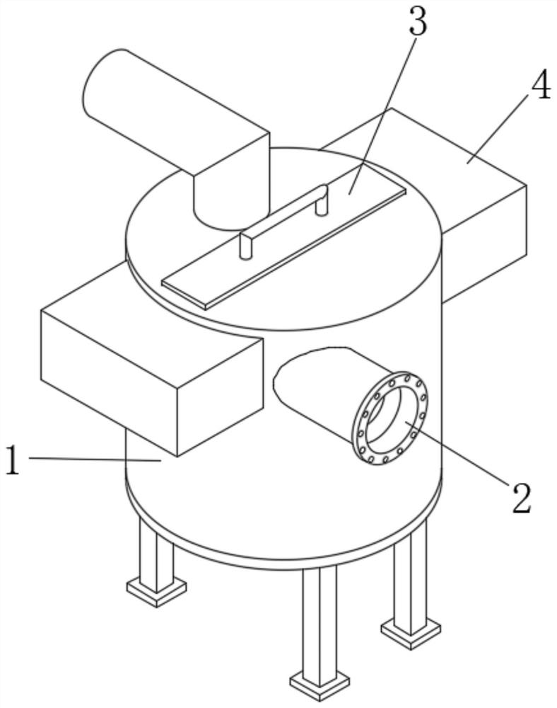
[0004] The purpose of the present invention is to solve the disadvantages of the poor use effect of the swirl type spark arrester in the prior art and the low efficiency of eliminating spark particles contained in the flue gas, and the proposed swirl insert spark arrester device

Method used


Image

  • Rotational flow plugboard spark trap
  • Rotational flow plugboard spark trap
  • Rotational flow plugboard spark trap

Examples


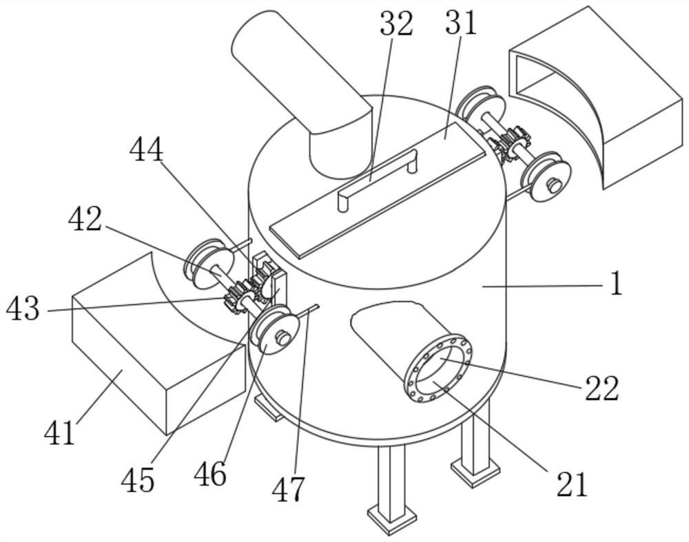
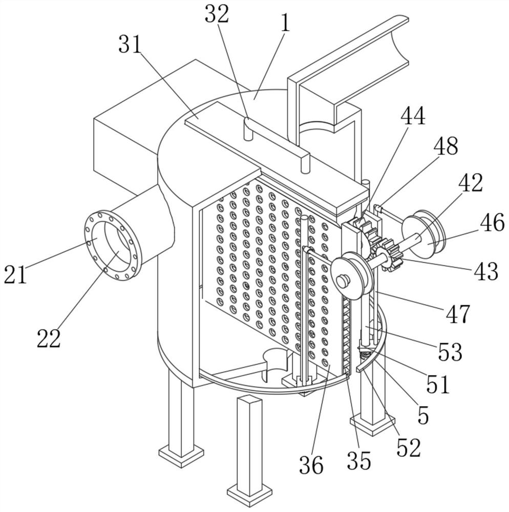
Embodiment Construction

[0027] The following will clearly and completely describe the technical solutions in the embodiments of the present invention with reference to the accompanying drawings in the embodiments of the present invention. Obviously, the described embodiments are only some, not all, embodiments of the present invention.

[0028] refer to Figure 1-8 , the swirl plate spark arrester, including the spark arrester main body 1, the input end of the spark arrester main body 1 is equipped with a swirl flow mechanism 2, the swirl flow mechanism 2 includes a delivery pipe 21, and the end of the delivery pipe 21 is close to the inlet The inner wall is fixedly connected with a pressurized frame 22, and the inner wall of one end of the delivery pipe 21 near the outlet is equipped with a guide fixed frame 23, and the inner wall of the guide fixed frame 23 is fixedly connected with a guide vane 24, and the guide vane 24 is close to the booster frame 22 One side of the center position is fixedly co...


PUM


Abstract

The invention discloses a rotational flow plugboard spark trap, which comprises a spark trap main body, a rotational flow mechanism is installed at the input end of the spark trap main body, the rotational flow mechanism comprises a conveying pipe, and a pressurizing frame is fixedly connected to the inner wall of one end, close to an inlet, of the conveying pipe. Smoke can be guided into the spark trap main body through the conveying pipe, and the flow speed of the smoke can be effectively increased when the smoke passes through the interior of a pressurization frame, so that the centrifugal force of spark particles can be increased, and the collision strength between the spark particles and the inner wall of the spark trap main body is improved; when the smoke passes through the interiors of a first stainless steel pore plate and a second stainless steel pore plate, the kinetic energy of sparks is reduced, the spark particles are effectively extinguished and the kinetic energy is effectively removed in the collision process, the spark particles can be settled and discharged, and the spark particle capturing efficiency is improved; and meanwhile, the first stainless steel pore plate and the second stainless steel pore plate are designed to be in a plug-in type, so that the cleaning is convenient.

Description

technical field [0001] The invention relates to the technical field of spark capture, in particular to a spark arrester with a swirl insert. Background technique [0002] The spark arrestor is mainly used on the bag filter, and is generally installed in front of the inlet of the dust collector. Its main function is to treat some high-temperature flue gas containing sparks, so as to reduce and eliminate the sparks in the flue gas. In order to prevent the spark particles in the flue gas from burning the dust filter bag in the bag filter accessories when the dust collector is processing the flue gas, the cost of flue gas treatment can be greatly reduced by using the spark arrester. The spark arrester can Divided into a variety of structural forms, there are three main groups in the existing market, namely swirl type, louver type and gravity settlement type. [0003] The existing swirling spark arrester uses the centrifugal force generated by the smoke to rotate around the insi...

Claims


Application Information

Patent Timeline
Patent Type & Authority Applications(China)
IPC IPC(8): B01D50/00B01D45/02B01D45/04B01D45/14B01D45/18B01D46/00B01D46/12
CPCB01D46/0093B01D45/14B01D45/02B01D45/04B01D45/18B01D46/12
Inventor 陈浩冰张双
Owner 格鼎机电有限公司
Learn More