
Sand screening and classifying equipment for buildings

A technology for screening and classification, construction, applied in the direction of filter screen, solid separation, grille, etc., can solve the problems of difficult centralized collection, high labor intensity, easy mixing, etc., to achieve easy installation and disassembly, reduce labor intensity, and simple operation Effect

Inactive Publication Date: 2021-11-09
云南六洲建筑劳务有限公司
View PDF0 Cites 0 Cited by
  • Summary
  • Abstract
  • Description
  • Claims
  • Application Information

AI Technical Summary

Problems solved by technology

[0003] In order to improve the efficiency of screening, commonly used sand screening and classification equipment requires continuous feeding of manpower, which is labor-intensive. Sands with different fineness modulus are easy to mix and difficult to collect centrally, thus reducing the efficiency of screening. , the practicability is not high, so there is a need for a sand screening equipment that can reduce labor intensity, greatly improve screening efficiency and facilitate centralized collection

Method used


Image

  • Sand screening and classifying equipment for buildings
  • Sand screening and classifying equipment for buildings
  • Sand screening and classifying equipment for buildings

Examples


Embodiment 1

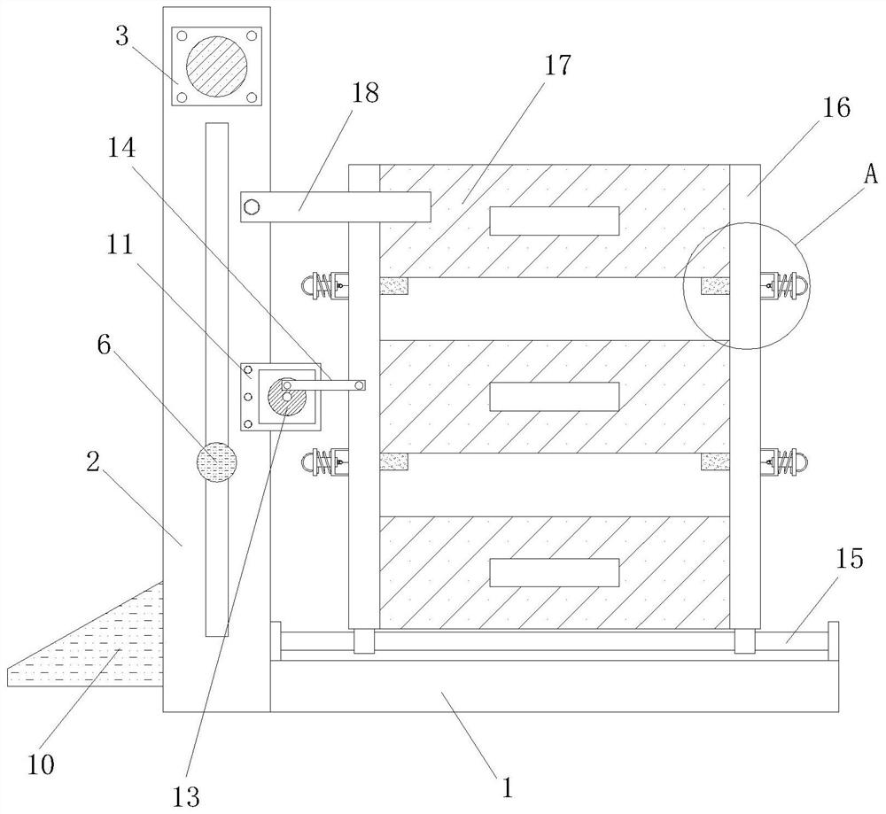
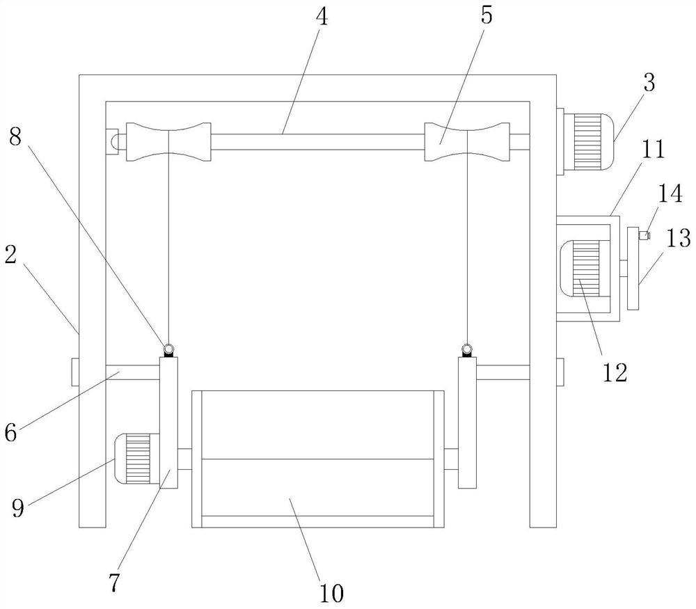
[0038] Embodiment one, such as figure 1 As shown, the front and back of the base 1 are provided with rectangular slots, and the two sets of limit rods 6 extend through the corresponding rectangular slots to the outside, and end plates are installed at the end of the extension section, and the hanging plate 7 passes through the limit The position bar 6 and the end plate are connected with the supporting frame 2, and through the setting of this structure, the stability during the lifting process of the hanging plate 7 can be maintained during use.

Embodiment 2

[0039] Embodiment two, such as Figure 4 , Figure 7 with Figure 8 As mentioned, the other end of the spring 21 is equipped with a locking lever 22, and one end of the locking lever 22 is threaded with a second suspension ring 23, and the inner rotation of the housing 16 is equipped with a stopper 24, and a third suspension ring 25 is installed on the surface of the stopper 24. The outer surface of the housing 16 is provided with a mounting groove, and the inside of the mounting groove is rotated to install a power rod, the surface of the power rod is equipped with a guide wheel 26, and the opposite end of the second suspension ring 23 and the third suspension ring 25 is equipped with a stay rope 27, By adopting the stopper 24 to separate the three groups of screens 17, it is possible to avoid overlapping and friction between the screens 17 to affect the screening effect, and it is also convenient to install and disassemble the screens 17.

[0040] Working principle: when i...


PUM


Abstract

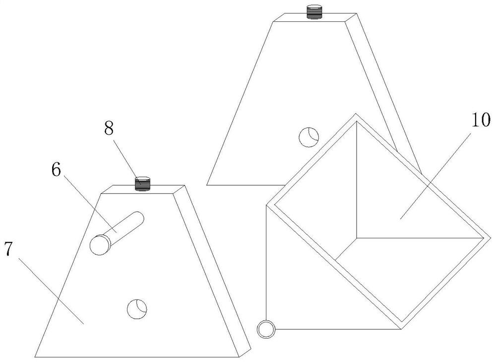
The invention discloses sand screening and classifying equipment for buildings. The sand screening and classifying equipment comprises a base, a supporting frame is installed at the left side of the base, a first motor is installed on the upper portion of the front face of the supporting frame, and a transmission rod is installed at the power output end of the first motor; and the other end of the transmission rod penetrates through the side edge of the supporting frame and is rotationally installed on the inner side wall of the supporting frame, two sets of winding wheels are symmetrically installed on the surface of the transmission rod, limiting rods are slidably installed on the front face and the back face of the supporting frame correspondingly, and hanging plates are installed at the opposite ends of the two sets of limiting rods correspondingly. According to the and screening and classifying equipment, the first motor drives the transmission rod to rotate, so that the transmission rod drives a feeding hopper to ascend, when the feeding hopper reaches a specified height, a second motor drives the feeding hopper to turn over, then to-be-screened sand in the feeding hopper is guided into a screen on the top layer, and the screening efficiency is guaranteed through circulating feeding; and in the process, the sand only needs to be manually poured into the feeding hopper, so that the labor intensity is greatly reduced.

Description

technical field [0001] The invention relates to the technical field of sand screening equipment, in particular to a construction sand screening and classification equipment. Background technique [0002] Sand is generally divided into natural sand and artificial sand. Rock particles formed by natural conditions (mainly rock weathering) with a particle size of less than 5 mm are called natural sand. Artificial sand is made by crushing rocks. Because of its high cost and many flakes and powders, it is generally not used. According to its different sources, natural sand can be divided into river sand, sea sand and mountain sand. The surface of mountain sand is rough, the particles are angular, the sand content is high, the content of organic impurities is also high, and the quality is poor. The surface of sea sand and river sand is smooth, but the salt content of sea sand is high, which has a certain impact on concrete and mortar. River sand is relatively clean and widely use...

Claims


Application Information

Patent Timeline
Patent Type & Authority Applications(China)
IPC IPC(8): B07B1/28B07B1/42B07B1/46
CPCB07B1/28B07B1/42B07B1/46B07B1/4609B07B2201/04
Inventor 不公告发明人
Owner 云南六洲建筑劳务有限公司
Learn More