Pipe pile mold cover cleaning device

A technology for cleaning devices and pipe pile molds, applied in cleaning methods and tools, cleaning methods using tools, chemical instruments and methods, etc., can solve the problems of unstable transition transmission, cleaning equipment, transmission equipment damage, low degree of automation, etc. , to achieve the effect of reducing labor intensity and labor cost, facilitating fine cleaning and high degree of automation

Pending Publication Date: 2021-11-09
湖南比克智能装备有限公司
View PDF0 Cites 0 Cited by
  • Summary
  • Abstract
  • Description
  • Claims
  • Application Information

AI Technical Summary

Problems solved by technology

[0003] 1. In the prior art, some are removed by manual cleaning, which is labor intensive, low work efficiency and high labor cost
[0004] 2. The degree of automation is low, and it cannot be connected with the transmission system to complete automatic cleaning, which seriously affects the realization of automatic production of pipe piles
[0005] 3. The cleaning effect is poor. Because there is cement slag left on the mold cover, it may have solidified, which makes the cleaning and removal not clean, resulting in residue, which affects the subsequent reuse of the mold cover, and then affects the production quality of the next batch of pipe piles
Such a long mold cover may be partially deformed and lifted when it is transported and cleaned in a straight line, which makes it impossible to contact and clean every place, which means that the cleaning effect is poor.
[0007] 5. If the cleaning device and the automatic transmission line are to be connected, how to ensure the transmission stability of the mold cover is also a problem during the connection process
For example, the transmission speed of the cleaning device is inconsistent with the transmission speed of the automatic transmission line, resulting in unstable transition transmission, which is easy to cause damage to the mold cover, cleaning equipment, and transmission equipment, and affects the service life of the equipment.

Method used


Image

  • Pipe pile mold cover cleaning device
  • Pipe pile mold cover cleaning device
  • Pipe pile mold cover cleaning device

Examples


Embodiment Construction

[0035] The present invention will be further described in detail below in conjunction with the accompanying drawings and specific embodiments.

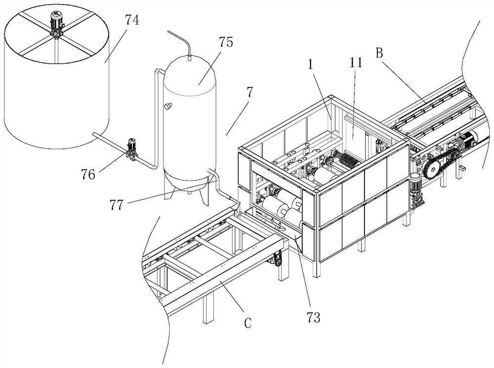
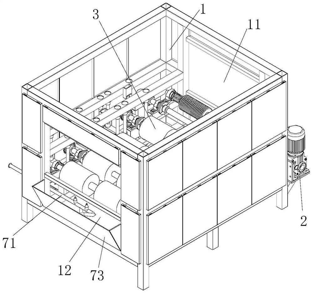
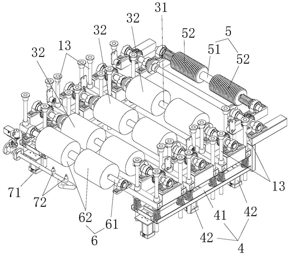
[0036] Such as Figure 1 to Figure 5 As shown, the present invention provides a pipe pile form cover cleaning device, including a frame 1 and a housing, the frame 1 is provided with a fixing assembly for fixing the housing, and the height of the frame 1 is between 0.5 meters and 10 meters . The casing is provided with an input port 11 and an output port 12 one after the other for docking with external transmission equipment, that is, the front and rear ends of the frame 1 are provided with external transmission equipment, such as automatic transmission lines, automatic chain conveyors, etc. The frame 1 is provided with a drive assembly 2 and a plurality of cover brush assemblies 3 arranged in sequence. The drive assembly 2 is used to drive a plurality of cover brush assemblies 3 to roll to carry the cover conveyed from the input port...


PUM


Abstract

The invention discloses a pipe pile mold cover cleaning device. The pipe pile mold cover cleaning device comprises a rack and a shell, wherein an input port and an output port which are arranged front and back and used for being in butt joint with external conveying equipment are formed in the shell; a driving assembly and a plurality of mold cover brush assemblies arranged in sequence are arranged in the rack; the driving assembly is used for driving the plurality of mold cover brush assemblies to roll so as to bear mold covers conveyed from the input port and convey the mold covers to the output port; and each mold cover brush assembly comprises a transmission shaft and a bristle part arranged on the circumferential face of the transmission shaft so as to be used for conducting rolling brushing cleaning on the mold covers synchronously during rolling conveying. The pipe pile mold cover cleaning device has the advantages of being simple and compact in structure, convenient and flexible to operate, good in cleaning effect, good in adaptability and high in integration degree.

Description

technical field [0001] The invention mainly relates to the field of pipe pile production equipment, in particular to a pipe pile mold cover cleaning device. Background technique [0002] In current construction work, pipe piles need to be used in large quantities. During the production of pipe piles, mold covers will be used. The mold cover can be recycled many times. After the mold cover is used once, there will be cement residue in the enclosed contact of the two mold covers. If these cement residues are not cleaned and removed in time, it will affect the subsequent reuse of the formwork, thereby affecting the production quality of the next batch of pipe piles, and may even cause a major risk of safety accidents in subsequent construction. The current mold cover cleaning operation has the following technical problems: [0003] 1. In the prior art, some of them are removed by manual cleaning, which has high labor intensity, low work efficiency and high labor cost. [0...

Claims


Application Information

Patent Timeline
Patent Type & Authority Applications(China)
IPC IPC(8): B08B1/04B08B1/00B08B13/00
CPCB08B1/04B08B13/00B08B1/002
Inventor 陈壮武
Owner 湖南比克智能装备有限公司
Why Eureka
Try Eureka