High-precision stamping die for sheet metal part machining

A technology for stamping dies and sheet metal parts, which is applied in the direction of metal processing equipment, forming tools, manufacturing tools, etc. It can solve the problem that high-precision stamping dies cannot be stamped and formed, they do not have the function of supplementing and collecting sheet metal parts, and the stamping device cannot stamp at the same time and drawing problems to achieve the effect of improving accuracy and quality

Inactive Publication Date: 2021-11-09
万腾钣金(深圳)有限公司
View PDF1 Cites 2 Cited by
  • Summary
  • Abstract
  • Description
  • Claims
  • Application Information

AI Technical Summary

Problems solved by technology

[0004] Most of the traditional high-precision stamping dies for sheet metal processing need to manually pick and place the sheet metal parts. They do not have the function of replenishing and collecting sheet metal parts, and the safety and production efficiency are low. At the same time, the existing high The precision

Method used


Image

  • High-precision stamping die for sheet metal part machining
  • High-precision stamping die for sheet metal part machining
  • High-precision stamping die for sheet metal part machining

Examples


no. 1 example

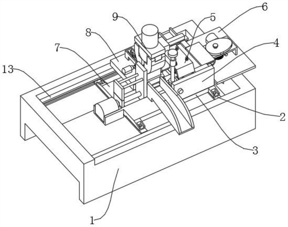
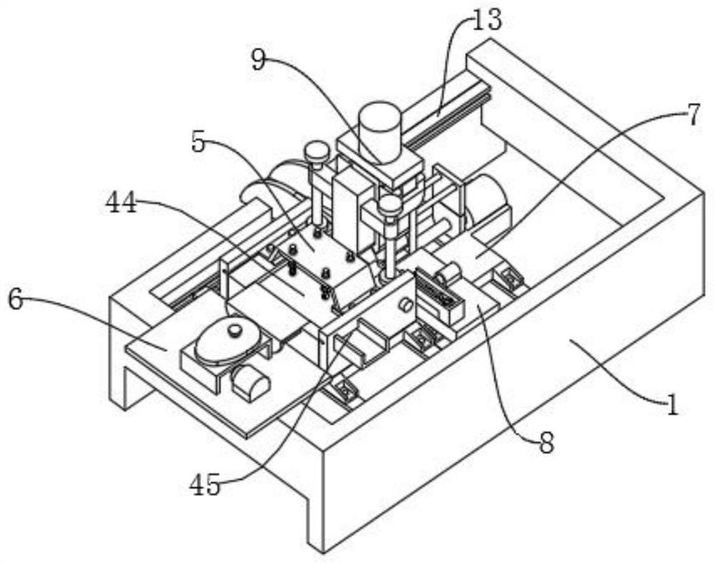
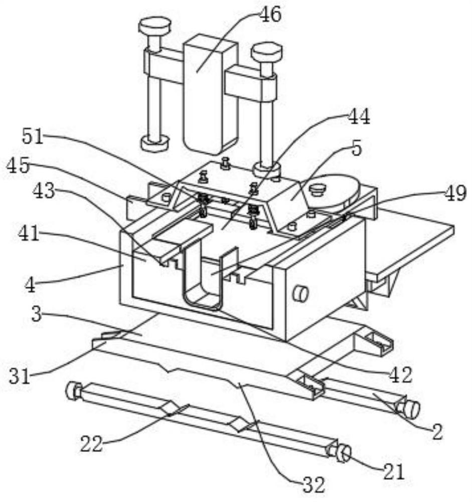
[0023] Such as Figure 1 to Figure 6 As shown, the present invention provides a high-precision stamping die for sheet metal processing, which includes a mold bottom frame 1, one end of the top of the mold bottom frame 1 is provided with an installation top groove 11, and the other end of the top of the mold bottom frame 1 is provided with a positioning chute 12. The inner side of the top of the mold bottom frame 1 is integrally provided with a load-bearing support frame 13, and the inner side of the load-bearing support frame 13 is provided with a load-bearing slot 14, and the inner side of the load-bearing slot 14 is slidingly installed with a load-bearing bottom column 2, and the two ends of the load-bearing bottom column 2 are connected The shaft is equipped with a driving mechanism 21, and the driving mechanism 21 meshes with the load-bearing tooth groove 14 to move; the top of the load-bearing bottom column 2 is provided with a positioning slot 22, and the load-bearing bot...

no. 2 example

[0035] In the stamping process of sheet metal parts with different thicknesses, it is often not only necessary to use dies to stamp the sheet metal parts into workpieces with a certain shape, but also to stretch the workpieces after the preliminary stamping and forming, so that the preliminary stamping and forming workpieces produce plastic deformation. , to produce workpieces with specified shapes and properties; in actual production, the corresponding drawing device is often used to stretch the stamped workpiece after the workpiece is stamped. On the one hand, the stamping and drawing processes are operated separately , to reduce the production efficiency of the workpiece; secondly, an additional drawing device is required to increase the production cost; therefore, by further optimizing the device, the device has the functions of stamping and drawing at the same time, so as to improve production efficiency, reduce production cost, and improve functionality of the device.

...


PUM


Abstract

The invention belongs to the technical field of sheet metal machining, and discloses a high-precision stamping die for sheet metal part machining, which comprises a die bottom frame, wherein a mounting top groove is formed in one end of the top of the die bottom frame, a position adjusting sliding groove is formed in the other end of the top of the die bottom frame, and a bearing support frame is integrally arranged on the inner side of the top of the die bottom frame; a bearing tooth groove is formed in the inner side of the bearing support frame, a bearing bottom column is slidably installed on the inner side of the bearing tooth groove, driving mechanisms are installed at the two ends of the bearing bottom column through connecting shafts, and the driving mechanisms and the bearing tooth groove move in an engaged mode; a servo motor drives the gear and the rack to rotate so as to drive a transportation pushing piece to slide in a reciprocating mode, the transportation pushing piece pushes extruded sheet metal parts and moves the extruded sheet metal parts to the inner side of a transportation sliding frame, then the sheet metal parts slide directionally and are collected in a centralized mode, so that the problems that an existing device needs manual collection, and safety and production efficiency are low are solved. The device can stretch the sheet metal parts while stamping the sheet metal parts, and is rich in function and high in efficiency.

Description

technical field [0001] The invention belongs to the technical field of sheet metal processing, in particular to a high-precision stamping die for sheet metal processing. Background technique [0002] Sheet metal is a comprehensive cold processing process for metal sheets, including shearing, punching / cutting / compositing, folding, welding, riveting, splicing, forming, etc. Sheet metal parts are products processed through sheet metal technology. [0003] The Chinese invention patent with the application number CN201810712178.7 discloses a stamping die for sheet metal parts, including an upper die, a lower die, and a die; both sides of the upper die are provided with a flattening unit, which includes The groove is connected with a rotating rod in the groove, and the rotating rod is provided with a turntable, an external thread part, and a circular plate in turn, and the turntable can flatten the sheet metal; the upper part of the first chamber is equipped with nuts, guide rails...

Claims


Application Information

Patent Timeline
IPC IPC(8): B21D37/08B21D45/02B21D43/02B21D43/20
CPCB21D37/08B21D45/02B21D43/02B21D43/20
Inventor 张永聪王家兴李昊庞蒲开梅
Owner 万腾钣金(深圳)有限公司
Why Eureka
Try Eureka