
Heat dissipation device for machine tool assembly

A technology for heat sinks and components, applied in metal processing machinery parts, maintenance and safety accessories, metal processing equipment, etc., can solve the problems of inability to dispose of waste chips, generalization of heat dissipation effect, improvement of equipment performance or low maintenance effect, etc. Achieve the effect of reducing limitations, improving applicability, and facilitating accurate positioning

Pending Publication Date: 2021-11-09
QUZHOU UNIV
View PDF0 Cites 1 Cited by
  • Summary
  • Abstract
  • Description
  • Claims
  • Application Information

AI Technical Summary

Problems solved by technology

[0004] The purpose of the present invention is to solve the shortcomings in the prior art, such as: 1. The device lacks the function of cooling the most critical spindle of the machine tool, and the effect of improving or maintaining the performance of the equipment is low; 2. The cooling method of the device The function is relatively simple, the heat dissipation effect is generalized, and the waste chips that appear during the machining of the spindle cannot be processed, so a heat dissipation device for machine tool components is proposed

Method used


Image

  • Heat dissipation device for machine tool assembly
  • Heat dissipation device for machine tool assembly
  • Heat dissipation device for machine tool assembly

Examples


Embodiment Construction

[0032]The following will clearly and completely describe the technical solutions in the embodiments of the present invention with reference to the accompanying drawings in the embodiments of the present invention. Obviously, the described embodiments are only some, not all, embodiments of the present invention. Based on the embodiments of the present invention, all other embodiments obtained by persons of ordinary skill in the art without creative efforts fall within the protection scope of the present invention.

[0033] In describing the present invention, it should be understood that the terms "upper", "lower", "front", "rear", "left", "right", "top", "bottom", "inner", " The orientation or positional relationship indicated by "outside", etc. is based on the orientation or positional relationship shown in the drawings, and is only for the convenience of describing the present invention and simplifying the description, rather than indicating or implying that the referred devi...


PUM


Abstract

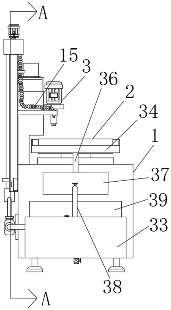
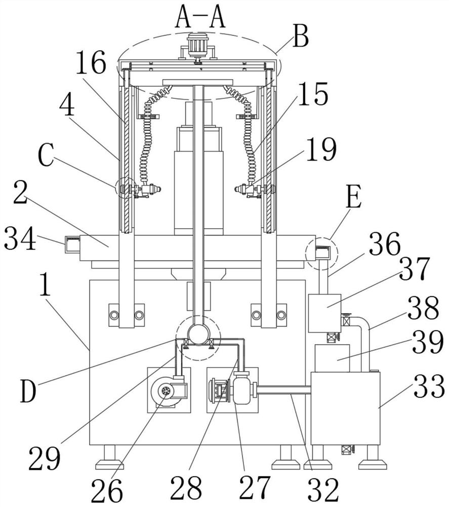
The invention discloses a heat dissipation device for a machine tool assembly, and relates to the technical field of heat dissipation of machine tools. The heat dissipation device comprises a machine tool body, a machining table is installed at the top end of the machine tool body, a main shaft body is installed on the surface of the machine tool body, a processing box is arranged at the top end of the main shaft body, two sets of rotating boxes are fixedly connected to the bottom end of the processing box, a first motor is installed at the top end of the processing box; an output shaft of the first motor extends into the processing box, a first rotating rod is arranged in the processing box, and the two sides of the first rotating rod are connected with the inner wall of the interior of the processing box through embedded bearings. According to the heat dissipation device, a user can conveniently carry out cooling and heat dissipation on the main shaft body in a processing state, can flexibly select air cooling and water cooling according to the time consumption of part processing and the quantity of generated sweeps, and can adjust the orientation of a spray head according to the height of the part and the main shaft body, so that accurate positioning is facilitated.

Description

technical field [0001] The invention relates to the technical field of heat dissipation of machine tools, in particular to a heat dissipation device for machine tool components. Background technique [0002] The machine tool is one of the necessary equipment in the mechanical processing industry. The performance of the machine tool, such as thermal performance, has become one of the most important factors affecting the performance of the high-speed machine tool. The machine tool spindle is the key functional component of the machine tool, mainly referring to It is the axis on the machine tool that drives the workpiece or tool to rotate. As the main shaft of the key functional part of the machine tool, its thermal characteristics determine the cutting speed and machining accuracy of the machine tool to a large extent, and are the most important factors affecting the improvement of the machine tool accuracy. [0003] Existing patent: A heat dissipation device for energy-saving...

Claims


Application Information

Patent Timeline
IPC IPC(8): B23Q11/12B23Q11/00B23Q11/10
CPCB23Q11/127B23Q11/0042B23Q11/1069
Inventor 邓小雷林晓亮陈昱珅郭术鹏郑嘉聪盛晓波顾珈怡王建臣谢长雄
Owner QUZHOU UNIV
Learn More