A surface treatment device for steel wire rope

A technology of surface treatment device and steel wire rope, which is applied in the direction of grinding drive device, grinding/polishing safety device, grinding machine tool parts, etc., can solve the problems of gap grinding treatment, large amount, and reduce the treatment effect of surface treatment device, etc., to achieve Effects of reducing resistance, reducing contact area, improving handling effect and use value

Active Publication Date: 2021-12-21
南通飞神金属制品有限公司
View PDF6 Cites 0 Cited by
  • Summary
  • Abstract
  • Description
  • Claims
  • Application Information

AI Technical Summary

Problems solved by technology

[0003] During the long-term storage of the existing steel wire rope, its surface will be corroded by humid air, resulting in an embroidery layer. In order to ensure the use value of the steel wire rope, the surface needs to be polished to remove the embroidery layer. The existing surface The processing device generally uses a grinding block to polish the surface of the steel wire rope. However, the steel wire rope is a spiral steel wire bundle twisted together by a plurality of steel wires according to certain rules. There are gaps between the steel wires. The existing grinding block only Only the outer wall of the steel wire rope can be polished, and the gap cannot be polished. As a result, there are still a large number of embroidered layers on the outer wall of the steel wire rope after surface treatment, which reduces the treatment effect of the surface treatment device.

Method used


Image

  • A surface treatment device for steel wire rope
  • A surface treatment device for steel wire rope
  • A surface treatment device for steel wire rope

Examples


Embodiment Construction

[0030]The following will clearly and completely describe the technical solutions in the embodiments of the present invention with reference to the accompanying drawings in the embodiments of the present invention. Obviously, the described embodiments are only some, not all, embodiments of the present invention.

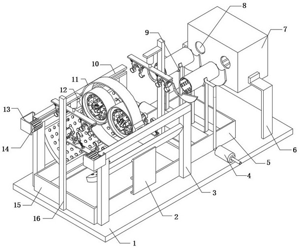
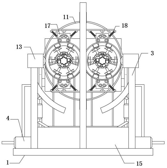
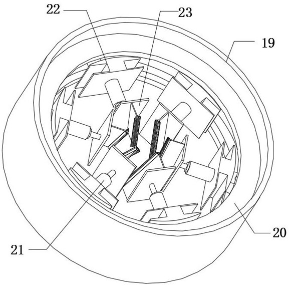
[0031] refer to Figure 1-4 , a surface treatment device for steel wire ropes, comprising a base 1 and a sliding frame 11, the inner wall of the sliding frame 11 is fixedly connected with two outer layers 19, and the inner walls of the two outer layers 19 are fixedly connected with annular sliding rails 20, The inner wall of the annular slide rail 20 is slidably connected with spin blocks 27 at equal distances, and the outer wall of each spin block 27 is fixedly connected with a conical head 26 at an equal distance. The conical head 26 is in contact with the inner wall of the annular slide rail 20. The outer walls of each spin block 27 are fixedly connected with a fix...


PUM


Abstract

The invention belongs to the technical field of steel wire rope surface treatment, in particular to a surface treatment device for steel wire ropes. The following proposal is now proposed, including a base and a sliding frame, and the inner wall of the sliding frame is fixedly connected with two outer layers. The present invention is provided with an embroidery slag cleaning component. After a section of steel wire rope is polished, the upper and lower cylinders are adjusted to drive the bending plate to press down and rise, and every two adjacent bending plates clamp the steel wire rope into it, so that the steel wire rope is passively bent. During the process, the oscillating spring is squeezed, and the cylinder drives the bending plate to reset. The oscillating spring oscillates repeatedly, thereby driving the impact head on the bending plate to impact the steel wire rope in different degrees, and the embroidered slag belt still attached after the surface is polished At the same time, the steel wire rope is transformed from a bent state to a stretched state, and the shock force generated also has the effect of cleaning up the embroidered slag, ensuring that there is no embroidered slag on the surface of the polished steel wire rope, and improving the grinding effect of the steel wire rope.

Description

technical field [0001] The invention relates to the technical field of steel wire rope surface treatment, in particular to a surface treatment device for steel wire ropes. Background technique [0002] The steel wire rope is a spiral steel wire bundle twisted together with steel wires whose mechanical properties and geometric dimensions meet the requirements according to certain rules. The steel wire rope is composed of steel wire, rope core and grease; The core is the center, and a certain number of strands are twisted into a helical rope. [0003] During the long-term storage of the existing steel wire rope, its surface will be corroded by humid air, resulting in an embroidery layer. In order to ensure the use value of the steel wire rope, the surface needs to be polished to remove the embroidery layer. The existing surface The processing device generally uses a grinding block to polish the surface of the steel wire rope. However, the steel wire rope is a spiral steel wir...

Claims


Application Information

Patent Timeline
Patent Type & Authority Patents(China)
IPC IPC(8): B24B27/033B24B55/06B24B41/02B24B41/06B24B27/00B24B47/08C23G3/02
CPCB24B27/033B24B55/06B24B41/02B24B41/067B24B27/0076B24B47/08C23G3/023
Inventor 陈聪明
Owner 南通飞神金属制品有限公司
Why Eureka
Try Eureka