Internal powder machine

A rack and vacuum technology, applied in the direction of conveyors, vibrating conveyors, conveyor objects, etc., can solve the problems of large particles or lumps of powder falling, poor economic benefits, short service life, etc., to avoid powder jamming Phenomenon, improvement of service life, effect of long service life

Active Publication Date: 2021-11-09
漳州迈邦自动化设备有限公司
View PDF12 Cites 2 Cited by
  • Summary
  • Abstract
  • Description
  • Claims
  • Application Information

AI Technical Summary

Problems solved by technology

[0002] In the existing internal powder machine, the motor drives the disc to rotate and convey the powder. If the powder is slightly damp, the powder will easily fall into large particles or lumps, resulting in uneven powder.
[0003] The utility model with the application number CN201920069153X discloses a powder vacuum conveying system, which provides a powder vacuum conveying sys

Method used


Image

  • Internal powder machine
  • Internal powder machine
  • Internal powder machine

Examples


Embodiment 1

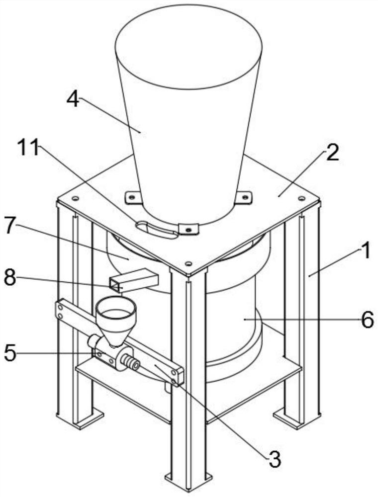
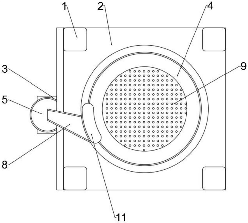
[0027] Such as figure 1 As shown, an internal powder machine proposed by the present invention includes a frame 1, an upper plate 2, a vacuum processor mounting frame 3, a hopper 4, a vacuum processor assembly 5, a vibrator 6, a vibrating plate assembly 7 and a discharge chute 8; the upper plate 2 is set on the frame 1; the hopper 4 is set on the upper plate 2; the vibrating plate assembly 7 driven by the vibrator 6 is set at the discharge end of the hopper 4; the discharge chute 8 is set on the vibrating plate assembly 7 The discharge end, the discharge chute 8 is located above the vacuum processor assembly 5; the vacuum processor mounting frame 3 is arranged on the frame 1; the vacuum processor assembly 5 is arranged on the vacuum processor mounting frame 3, and the vacuum processor assembly 5 includes a threaded rod 52; the threaded rod 52 is provided as a ceramic material.

[0028] In this embodiment, by setting the vibrator 6 and the vibrating plate assembly 7, the vibra...

Embodiment 2

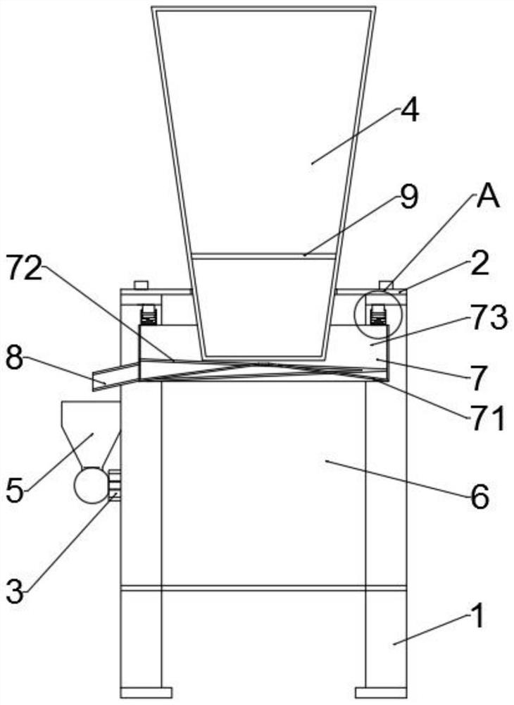
[0031] Such as Figure 1-2 As shown, the present embodiment proposes an internal powder machine. Compared with Embodiment 1, the vibration plate assembly 7 includes a material holding plate 71, a spiral frame 72 and a vibration plate 73; the material holding plate 71 and the spiral frame 72 are arranged on the vibration plate 73; the discharge end of the spiral frame 72 is arranged on the discharge end of the vibration plate 73, and is connected with the feed end of the discharge tank 8; the material holding plate 71 is arranged at the center of the spiral frame 72.

Embodiment 3

[0033] Such as figure 2 As shown, in the internal powder machine proposed in this embodiment, compared with Embodiment 2, the pitch of the screw frame 72 is 20 cm, the number of turns is 1, and the angle formed between the powder outlet end of the screw frame 72 and the horizontal plane is 13°.

[0034] In this embodiment, a spiral frame 72 is provided in the vibrating plate 73, the number of spiral turns is 1, and it rises in the vibrating plate with a pitch of 20; 13°, the powder will not become lumps, but the particles will be easily crushed into powder, and the powder will be conveyed evenly; the powder outlet will be tilted down, and the powder will not be piled up and conveyed smoothly and evenly, which is conducive to improving the efficiency of the internal powder machine. work efficiency.


PUM


Abstract

The invention relates to the technical field of powder conveying equipment, in particular to an internal powder machine. The machine comprises a rack, an upper plate, a vacuum processor mounting frame, a hopper, a vacuum processor component, a vibrator, a vibrating disc component and a discharging groove, wherein the vibrating disc component driven by the vibrator is arranged at the discharging end of the hopper; the discharging groove is formed in the discharging end of the vibration disc component and located above the vacuum processor component; the vacuum processor mounting rack is arranged on the rack; the vacuum processor component is arranged on the vacuum processor mounting frame and comprises a threaded rod; and the threaded rod is made of ceramic materials. The vibrator and the vibration disc component are arranged, the vibration frequency of the vibrator is controlled through a digital controller, and the vibration amplitude is convenient to adjust; a spiral frame is arranged in the vibration disc, powder cannot be blocky, particles are easily crushed into powder through vibration, and the powder is conveyed uniformly; and a powder outlet nozzle descends in an inclined mode, powder conveying is stable and uniform without accumulation, and the working efficiency of the internal powder machine is improved.

Description

technical field [0001] The invention relates to the technical field of powder conveying equipment, in particular to an internal powder machine. Background technique [0002] In the existing internal powder machine, the motor drives the disc to rotate and convey the powder. If the powder is slightly damp, the powder will easily fall into large particles or blocks, resulting in uneven powder. [0003] The utility model with the application number CN201920069153X discloses a powder vacuum conveying system, which provides a powder vacuum conveying system capable of stirring, screening and conveying the powder; conveying the powder to the designated equipment through the vacuum generator Internally, the vacuum generator material used in the existing technology has a short service life. If it is made of tungsten steel, although the service life of the equipment can be improved, the cost is too high and the economic benefit is poor. Contents of the invention [0004] Aiming at t...

Claims


Application Information

Patent Timeline
IPC IPC(8): B65G53/06B65G65/32B65G27/02B65G27/32B65G47/44B65G27/16B65D88/66B65G53/48
CPCB65G53/06B65G65/32B65G27/02B65G27/32B65G47/44B65G27/16B65D88/66B65G53/48
Inventor 王应建
Owner 漳州迈邦自动化设备有限公司
Why Eureka
Try Eureka