
Magnetic compass ellipse fitting error compensation method based on OPTICS algorithm

An ellipse fitting and error compensation technology, which is applied in compass, measuring device, surveying and navigation, etc., can solve the problems of insufficient protection of ellipse fitting accuracy, reduction of magnetic heading angle calculation accuracy, and great influence on algorithm results, etc. Achieve the effects of preventing pollution, preventing data storage errors, and enhancing flexibility

Inactive Publication Date: 2021-11-09
BEIJING INSTITUTE OF TECHNOLOGYGY
View PDF6 Cites 2 Cited by
  • Summary
  • Abstract
  • Description
  • Claims
  • Application Information

AI Technical Summary

Problems solved by technology

However, during the measurement process, because the sensor is affected by the surrounding environment and its own accuracy is limited, there may be singular error points in the original data set, which obviously deviate from the normal data in the coordinate system, resulting in a decline in the fitting accuracy in the later stage, thereby reducing The calculation accuracy of magnetic heading angle
In view of this problem, the existing magnetic compass ellipse fitting correction method that directly uses the original data cannot solve it well
[0006] In order to process the original data set, a least squares ellipse fitting algorithm based on the DBSCAN algorithm has appeared, which can compensate the real-time data of the magnetic compass to eliminate singular error points, but the DBSCAN algorithm in this scheme is only for a single singularity The error points are filtered, but a cluster of singular error points is not filtered, and the precision protection of the later ellipse fitting is not comprehensive enough. In addition, the two parameters in the DBSCAN algorithm - the domain radius ε and the minimum number of domain points to become the core object m has a great influence on the results of the algorithm. The magnetic compass needs to be adjusted in different usage scenarios, so the application scenarios of the algorithm are very limited.

Method used


Image

  • Magnetic compass ellipse fitting error compensation method based on OPTICS algorithm
  • Magnetic compass ellipse fitting error compensation method based on OPTICS algorithm
  • Magnetic compass ellipse fitting error compensation method based on OPTICS algorithm

Examples


Embodiment Construction

[0022] The present invention will be described in detail below in conjunction with the accompanying drawings.

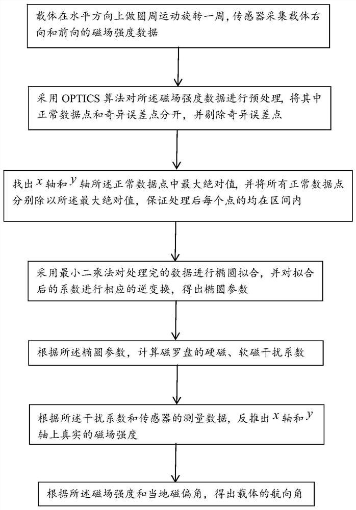
[0023] Such as figure 1 As shown, a magnetic compass ellipse fitting error compensation method based on the OPTICS algorithm in this specific embodiment, wherein the xyz axes of the three-axis magnetic compass point to the right, front, and upper directions of the carrier respectively. For the vehicle situation, only consider Error compensation in the horizontal direction of the x-axis and the y-axis, based on which the method specifically includes the following steps:

[0024] Step 1. The carrier rotates in a circular motion in the horizontal direction, and the sensor collects the right and forward magnetic field strength data H of the carrier. xm and H ym ;

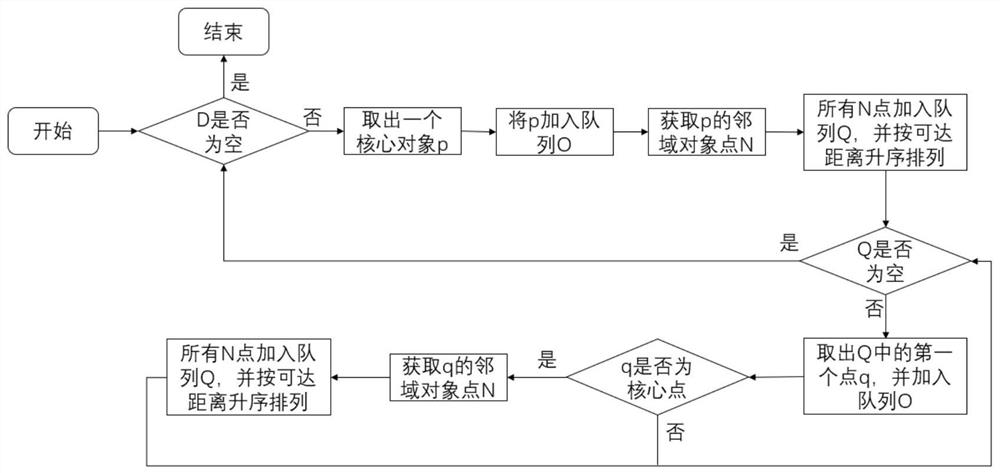
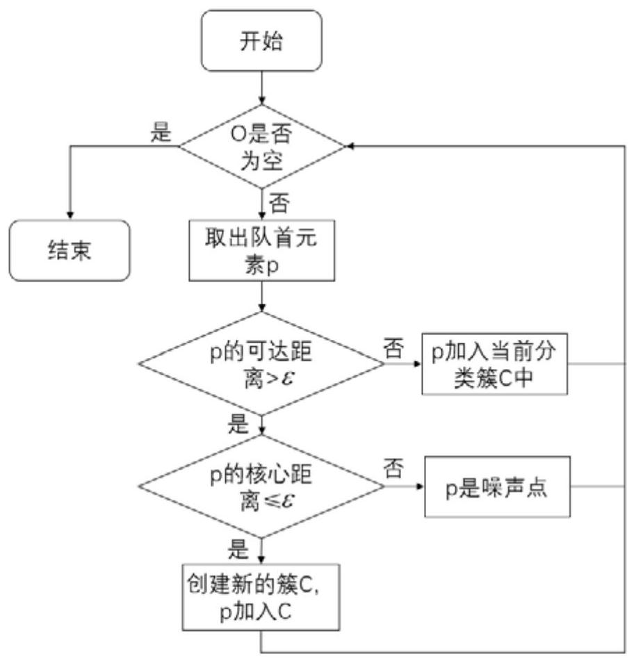
[0025] Step 2, using the OPTICS algorithm to preprocess the magnetic field strength data, separating the normal data points from the singular error points, and removing the singular error points; in the pre...


PUM


Abstract

The invention discloses a magnetic compass ellipse fitting error compensation method based on an OPTICS algorithm, and the method comprises the steps: 1, enabling a carrier to make circular motion and rotate for a circle in the horizontal direction, and enabling a sensor to collect the rightward and forward magnetic field intensity data of the carrier; 2, preprocessing the magnetic field intensity data by adopting the OPTICS algorithm, separating normal data points from singular error points, and eliminating the singular error points; 3, finding out the maximum absolute value in the normal data points of the x axis and the y axis, and dividing all the normal data points by the maximum absolute value; step 4, carrying out ellipse fitting on the processed data by adopting a least square method, and carrying out corresponding inverse transformation on a coefficient after fitting to obtain an ellipse parameter; 5, calculating hard magnetic and soft magnetic interference coefficients of the magnetic compass according to the ellipse parameters; 6, according to the interference coefficient and the measurement data of the sensor, reversely deducing the real magnetic field intensity; and step 7, obtaining the course angle of the carrier according to the magnetic field intensity and the local magnetic declination.

Description

technical field [0001] The invention belongs to the field of magnetic compass ellipse fitting and error compensation, and in particular relates to a magnetic compass ellipse fitting error compensation method based on an OPTICS algorithm, which is used to improve the calculation accuracy of a carrier heading angle. Background technique [0002] The vehicle navigation technology in the prior art usually combines an inertial navigation system (INS) and a global navigation satellite system (GNSS), and combines the advantages of the two to improve the accuracy of the system output results. However, in scenarios where the satellite signal is poor or there is no satellite signal, the observability of the heading angle error of the integrated navigation system is poor or unobservable, resulting in the divergence of the heading error. The magnetic compass does not require external input, and only calculates the current heading angle based on the geomagnetic vector information measure...

Claims


Application Information

Patent Timeline
Patent Type & Authority Applications(China)
IPC IPC(8): G01C17/38
CPCG01C17/38
Inventor 缪玲娟吴子昊周志强
Owner BEIJING INSTITUTE OF TECHNOLOGYGY
Learn More