Supercharge Your Innovation With Domain-Expert AI Agents!

Pressure tapping device of differential pressure measuring liquid level meter for cryogenic liquid storage tank

A technology of cryogenic liquid and liquid level gauge, applied in the field of differential pressure level gauge, can solve problems such as large gap and lack of use value of pressure taking device, so as to improve accuracy, improve heating and antifreeze effect, and improve extrusion effect Effect

Active Publication Date: 2021-11-09
南通三锐化工装备有限公司
View PDF5 Cites 0 Cited by
  • Summary
  • Abstract
  • Description
  • Claims
  • Application Information

AI Technical Summary

Problems solved by technology

[0003] When the existing differential pressure level gauge is used to take pressure inside the cryogenic liquid storage tank, it is necessary to install the gas phase guide head and the liquid phase guide head at the top and bottom of the cryogenic liquid storage tank. After the installation is completed, start to take When the pressure is high, because the liquid at the liquid phase guide head is in an unstable state, it is easy to cause a large gap between the value after the pressure measurement and the correct value. In order to improve the accuracy of the pressure measurement results, it is necessary to carry out Stable, so that it is in a stable state when it enters the liquid phase guide head, but the existing pressure taking device does not have this function, resulting in the lack of use value of the pressure taking device

Method used


Image

  • Pressure tapping device of differential pressure measuring liquid level meter for cryogenic liquid storage tank
  • Pressure tapping device of differential pressure measuring liquid level meter for cryogenic liquid storage tank
  • Pressure tapping device of differential pressure measuring liquid level meter for cryogenic liquid storage tank

Examples


Embodiment Construction

[0027] The following will clearly and completely describe the technical solutions in the embodiments of the present invention with reference to the accompanying drawings in the embodiments of the present invention. Obviously, the described embodiments are only some, not all, embodiments of the present invention.

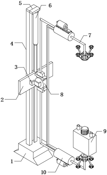
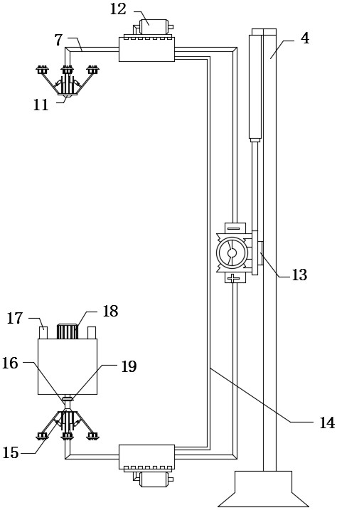
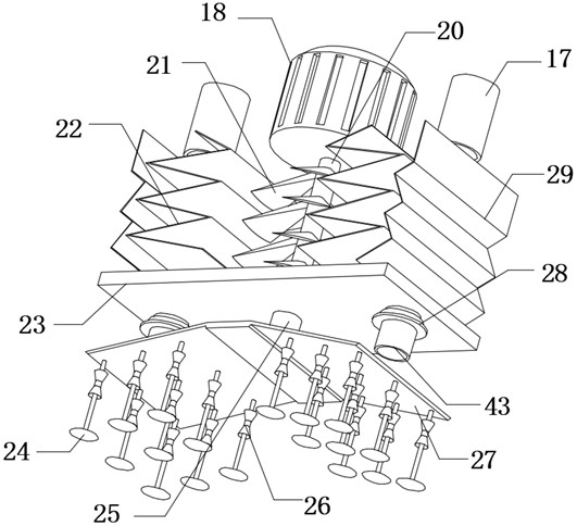
[0028] refer to Figure 1-3, a pressure-taking device for a differential pressure measuring liquid level gauge of a cryogenic liquid storage tank, including a mounting base 1 and a stabilizing box 9, the outer wall of the top of the stabilizing box 9 has two mounting holes, and the inner walls of the two mounting holes are A connecting pipe 17 is fixedly connected, a motor 18 is fixedly connected to the top outer wall of the stabilizing box 9, and the output shaft of the motor 18 is fixedly connected to a rotating shaft 20 through a coupling, and the outer wall of the rotating shaft 20 is fixedly connected to rotating blades 21 equidistantly. 9 The top inner wall bel...


PUM


Abstract

The invention belongs to the technical field of differential pressure liquid level meters, in particular to a pressure tapping device of a differential pressure measuring liquid level meter for a cryogenic liquid storage tank, and provides the following scheme that the pressure tapping device comprises a mounting seat and a stabilizing box, two mounting holes are formed in the outer wall of the top of the stabilizing box, and communicating pipes are fixedly connected to the inner walls of the two mounting holes. Through the arrangement of a heating cylinder, an air blower, an electric heating pipe, an annular heat conduction plate and an air blowing plate, after the differential pressure liquid level meter finishes pressure tapping, the electric heating pipe is powered on, heat is transmitted to the outer side of each guide pipe through the annular heat conduction plate, the guide pipes are heated, the differential pressure liquid level meter is prevented from being damaged due to the too low temperature of cryogenic liquid, in the heating process, the air blower is started, the air blower blows air into the heating cylinder through air blowing holes in the air blowing plate, the air is heated by the electric heating pipe and then makes contact with the outer wall of the guiding pipes, the heating anti-freezing effect is further improved, and the protection effect of the differential pressure liquid level meter is further improved.

Description

technical field [0001] The invention relates to the technical field of differential pressure liquid level gauges, in particular to a pressure acquisition device for differential pressure measuring liquid level gauges used in cryogenic liquid storage tanks. Background technique [0002] The differential pressure level gauge is an instrument that calculates the liquid level (differential pressure) of the object in the container by measuring the pressure difference at two different points in the container; the conventional differential pressure liquid level gauge measures the liquid level by measuring the liquid level pressure in the container Measurement. For example, a column of 500 mm of water corresponds to a pressure of 500 mmH20. However, in many applications there is additional vapor pressure above the liquid. Since vapor pressure is not part of the level measurement, it needs to be counteracted by the use of impulse tubes and capillaries with seals. [0003] When the...

Claims


Application Information

Patent Timeline
Patent Type & Authority Applications(China)
IPC IPC(8): G01F23/14G01L19/00
CPCG01F23/14G01L19/00
Inventor 蔡小洪郑健周松涛
Owner 南通三锐化工装备有限公司
Features
  • R&D
  • Intellectual Property
  • Life Sciences
  • Materials
  • Tech Scout
  • Unparalleled Data Quality
  • Higher Quality Content
  • 60% Fewer Hallucinations
Learn More