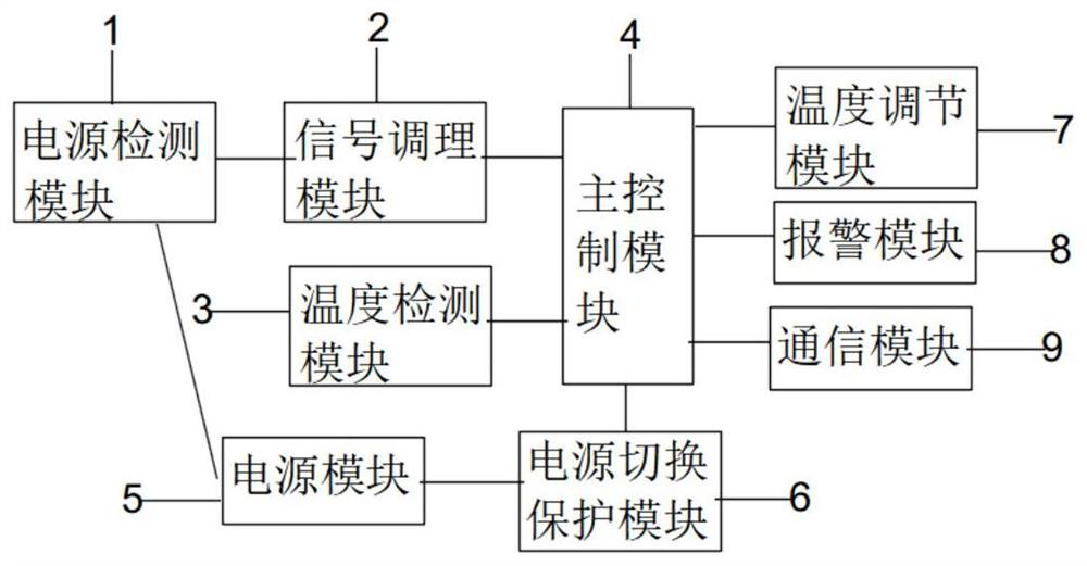
Signal tester protection circuit
A technology for signal testing and circuit protection. It is used in electrical measurement, power supply testing, circuit devices, etc. It can solve problems such as instrument burnout, decreased test accuracy, and decreased signal test accuracy, so as to prevent damage and avoid system failures.
- Summary
- Abstract
- Description
- Claims
- Application Information
AI Technical Summary
Problems solved by technology
Method used
Image
Examples
Embodiment 2
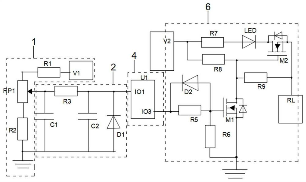
[0033] Embodiment 2: On the basis of Embodiment 1, please refer to figure 2 , in a specific embodiment of the signal tester protection circuit of the present invention, the power detection module 1 includes a first resistor R1, a second resistor R2 and a potentiometer RP1; the power module 5 includes a main power supply V1;
[0034] Specifically, the first end of the first resistor R1 is connected to the main power supply V1, the second end of the first resistor R1 is connected to the first end of the potentiometer RP1, and the second end of the potentiometer RP1 is connected to the ground through the second resistor R2.
[0035] Further, the signal conditioning module 2 includes a third resistor R3, a first capacitor C1, a second capacitor C2 and a first diode D1; the main control module 4 includes a first controller U1;
[0036] Specifically, the first end of the third resistor R3 is connected to the slider end of the potentiometer RP1 and the first end of the first capacit...
Embodiment 3
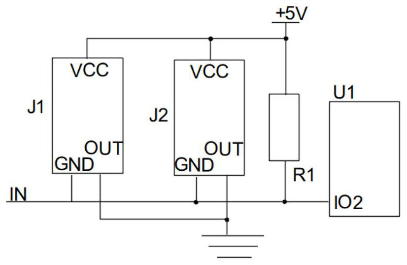
[0040] Embodiment 3: On the basis of Embodiment 2, please refer to image 3 , Figure 4 with Figure 5 , in a specific embodiment of the signal tester protection circuit of the present invention, the temperature detection module 3 includes a first temperature sensor J1, a second temperature sensor J2, a first power supply +5V and a fourth resistor R4;
[0041] Specifically, the first end of the first temperature sensor J1 and the first end of the second temperature sensor J2 are connected to the first power supply +5V and the first end of the first resistor R1, the second end of the first temperature sensor J1 is connected to the second The second end of the temperature sensor J2 is grounded, and the third end of the first temperature sensor J1 and the third end of the second temperature sensor J2 are connected to the second end of the main control module 4 .
[0042] Further, the temperature adjustment module 7 includes a first cooling unit 701 and a second cooling unit 702...
PUM
 Abstract
Description
Claims
Application Information
 - R&D
- Intellectual Property
- Life Sciences
- Materials
- Tech Scout
- Unparalleled Data Quality
- Higher Quality Content
- 60% Fewer Hallucinations
Browse by: Latest US Patents, China's latest patents, Technical Efficacy Thesaurus, Application Domain, Technology Topic, Popular Technical Reports.
© 2025 PatSnap. All rights reserved.Legal|Privacy policy|Modern Slavery Act Transparency Statement|Sitemap|About US| Contact US: help@patsnap.com


