Fixing device for cable laying

A fixing device and cable laying technology, applied in the direction of cable laying equipment, cable installation, cable accessories, etc., can solve the problems of reducing performance, high frequency vibration, affecting the service life, etc., to reduce the current magnetic effect, improve the use of performance, the effect of prolonging the service life

Inactive Publication Date: 2021-11-09
謝金吉
View PDF0 Cites 4 Cited by
  • Summary
  • Abstract
  • Description
  • Claims
  • Application Information

AI Technical Summary

Problems solved by technology

[0005] Aiming at the deficiencies of the prior art, the present invention provides a fixing device for cable laying, which solves the problem that the existing cable laying still adopts rigid fixing, especially when the cable transmits a large current, it will be affected by the magnetic effect of the current. High-frequency vibration, under long-term vibration, it is easy to loosen, and it will accelerate the wear and tear of the cable, affecting the service life. In severe cases, it will be damaged, resulting in leakage, which has a large safety hazard and reduces the performance.

Method used


Image

  • Fixing device for cable laying
  • Fixing device for cable laying
  • Fixing device for cable laying

Examples


Embodiment example 1

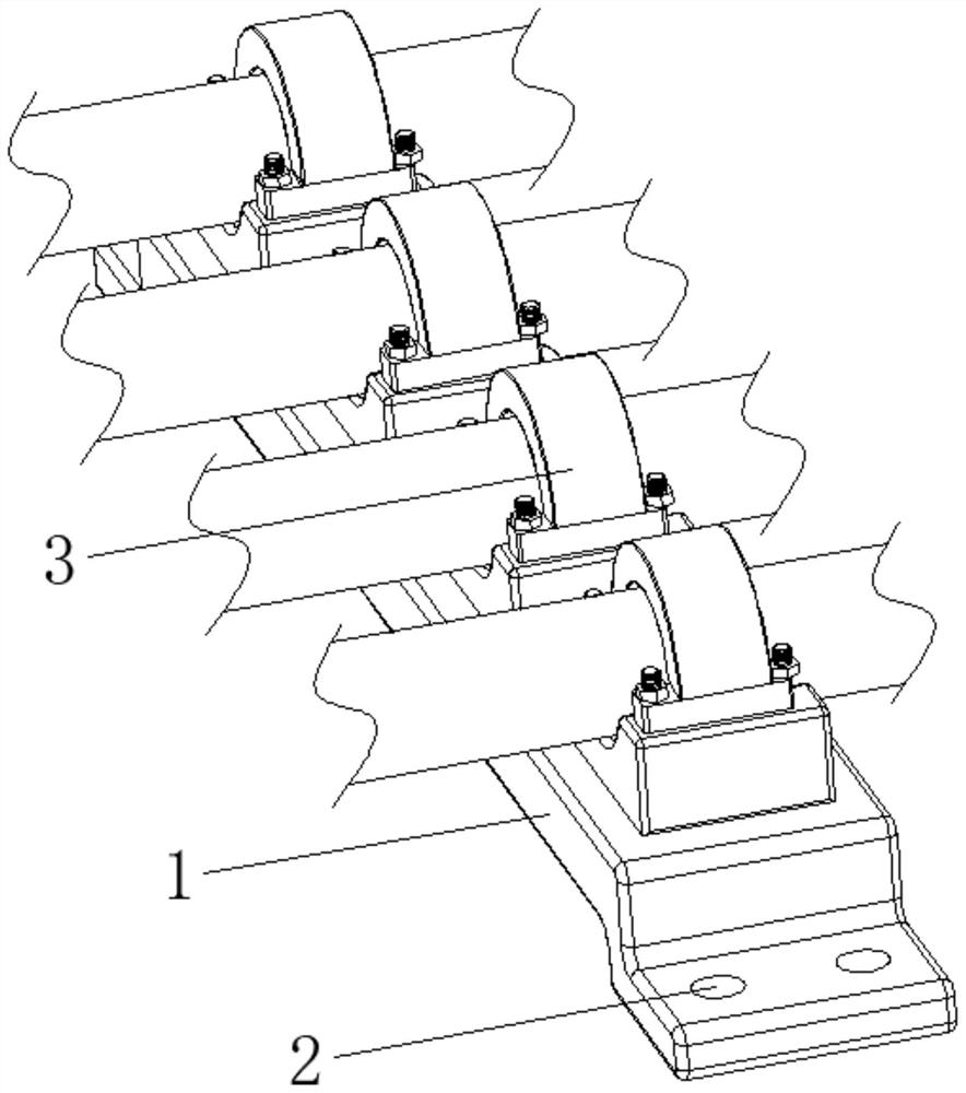
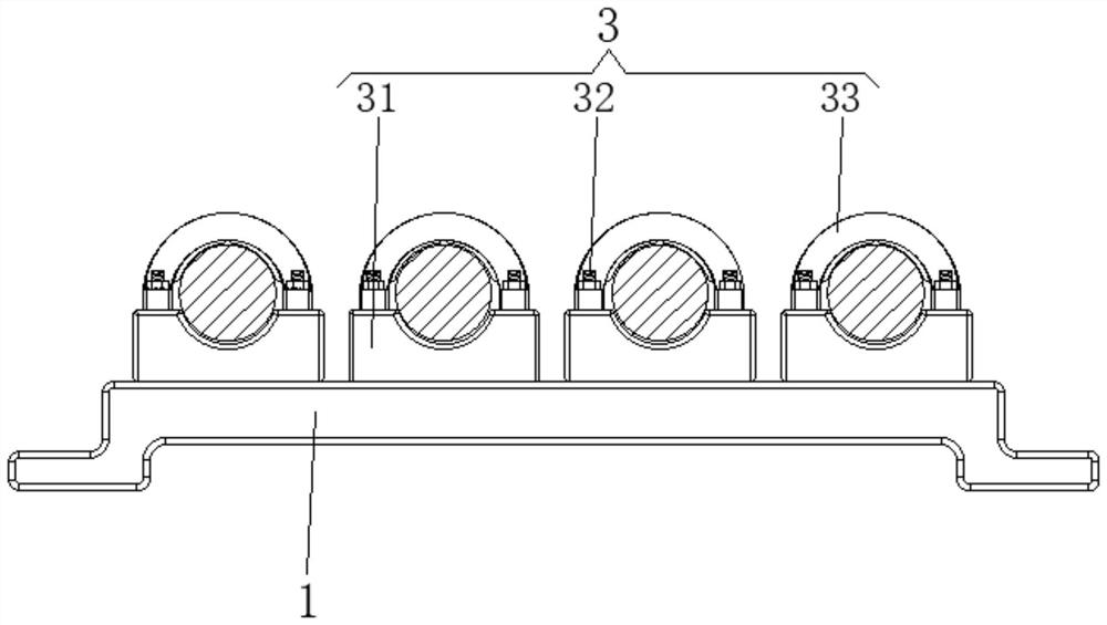
[0030] see Figure 1-6 , the present invention provides a technical solution: a fixing device for cable laying, comprising a mounting base 1, a fixing hole 2, and a line clamp device 3, the fixing holes 2 are set on the two sides corresponding to the bottom edge of the surface of the mounting base 1, The line card device 3 is arranged on the top of the installation base 1, and the line card devices 3 are evenly distributed on the top of the installation base 1;

[0031] The line card device 3 is provided with a limiting device 31, a connecting stud 32, and a pressing device 33. The bottom of the limiting device 31 is fixedly connected to the top of the installation base 1, and the bottom end of the connecting stud 32 is connected to the inside of the limiting device 31. And the position close to the end is fixedly connected, the pressing device 33 is matched and connected on the top of the limit device 31, the pressing device 33 is connected with the connecting stud 32 and fix...

Embodiment example 2

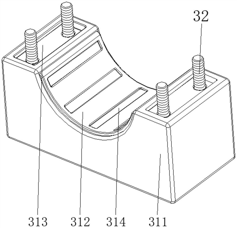
[0033] The limiting device 31 is provided with an arc groove limiting block 311, an anti-skid pad 312, a slide plate 313, and a flexible support device 314. fixed on the surface of the arcuate groove limiting block 311 and located at the groove position, the slide plate 313 is slidably connected inside the arcuate groove limiting block 311 and close to the top position, and the sliding plate 313 is connected with the connecting stud 32, The flexible supporting device 314 is arranged inside the arc groove limiting block 311 and is positioned at the position of the anti-skid pad 312. The bit block 311 cooperates to limit the cable, and at the same time, it is connected by the connecting stud 32 and locked by a nut. At this time, the anti-skid pad 312 has an anti-skid effect on the cable, and it is difficult to move at will. At the same time, the slide plate 313 It will be moved downward by the pressure of the pressing device 33, and then the pressure will be applied to the flexi...

Embodiment example 3

[0036] The pressing device 33 is provided with an arc-shaped pressing plate 331, a pressing key bar 332, and a pressurizing device 333. The pressing key bar 332 is fixed on the bottom end of the arc-shaped pressing plate 331. The booster device 333 is arranged on the inner wall of the arc-shaped pressure plate 331, and is stuck on the cable by the arc-shaped pressure plate 331, and cooperates with the arc-shaped groove limit block 311 through the key bar 332. After locking, the pressure The key bar 332 will press the slide plate 313, so that the cable is supported flexibly, and at the same time, according to the action force and reaction force, the pressure will also be applied to the booster device 333 at this time, which further helps to fix the cable without loosening Case.

[0037] The booster device 333 is provided with an arc panel 3331, a capsule body 3332, and a rubber layer 3333. One end of the arc panel 3331 is rotatably connected to the inner wall of the arc-shaped ...


PUM


Abstract

A fixing device for cable laying disclosed by the present invention comprises a mounting base, fixing holes and wire clamping devices, the fixing holes are formed in the two corresponding sides of the bottom edge of the surface of the mounting base, and the wire clamping devices are arranged at the top of the mounting base and are uniformly distributed at the top of the mounting base. The bottom of a limiting device is fixedly connected with the top of the mounting base, the bottom end of a connecting stud is fixedly connected with the position, close to the end, in the limiting device, a pressing device is connected to the top of the limiting device in a matched manner, and the pressing device and the connecting stud are connected in a matched manner and are fixed through a nut. The invention relates to the technical field of power construction devices. According to the fixing device for cable laying, the anti-vibration effect is achieved, the cable can be flexibly fixed and is not prone to being affected by a current magnetic effect, the vibration amplitude is effectively reduced, abrasion to a cable is reduced, the service life is prolonged, and the use performance is improved.

Description

technical field [0001] The invention relates to the technical field of electric power construction equipment, in particular to a fixing device for cable laying. Background technique [0002] All aspects of life are increasingly inseparable from electricity. In the infrastructure construction of power supply, safety and reliability are important factors in the construction of power infrastructure. With the gradual acceleration of the urbanization process, urban planning is becoming more and more modern. In the process of power supply for urban construction, cable laying has become the minimum construction requirement. Cable laying refers to the process of laying and installing cables along the surveyed route to form a cable route. According to the application occasion, it can be divided into several laying methods such as overhead, underground (pipeline and direct burial), underwater, wall and tunnel. Reasonable selection of cable laying method is very important to ensure ...

Claims


Application Information

Patent Timeline
Patent Type & Authority Applications(China)
IPC IPC(8): H02G1/06H02G15/007
CPCH02G1/06H02G15/007
Inventor 谢金吉
Owner 謝金吉
Why Eureka
Try Eureka